Dusting off my thread from last year regarding snowblowers . . .
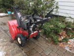
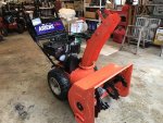
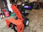
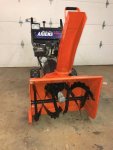
I sold off 2 snowblowers from my 'fleet' of 5. I sold an Ariens ST824LE and a Husqvarna ST224, both for pretty decent $$$. So, now I'm down to 3 machines, which feels rather scant as compared to last year.
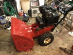
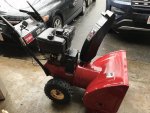
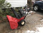
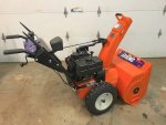
My Toro PowerShift 824 (OHV) is going to be my primary machine, the Troy-Bilt 2410 will be its back-up . . . and I relegated the 'tricked out' Toro 521 to the summer house on Cape Cod.

I wanted to put a headlight on the Toro 824 as it does have the electrical connector for a charging system. Similar to the challenges that I had last year, there is just one electrical lead coming out from under the cowl. I'm getting a somewhat odd looking sine wave from the connection, but it is about 30 volts peak-to-peak, so it should be able to run a decent LED utility light.
I have an Optronics TLL30FB light in mind . . . haven't bought it yet, but it is a 12 volt @ 0.75 amp load. Based on my prior year's experience of tapping into the Briggs 305cc power system on my Troy-Bilt, I decided to see if I can get a full wave rectifier to work in the circuit instead of just a simple diode.
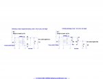
My plan was/is to try to put in an isolating (i.e. 1:1) transformer and 'float' the secondary, then tie the '-' lead of the rectifier to chassis ground. I'm not sure this will work, so I thought I would post the schematic for comment.
.
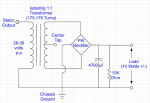
.
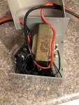
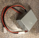
I had a spare 120v/12v transformer on hand, so I sacrificed its 'iron' to the cause and made my own isolating transformer with center tap on the secondary. I used 24 GA magnetic wire and did 175 turns on the primary and 175 turns (87/88) on the secondary windings, then re-assembled the iron and casing. I tried a couple configurations of the above schematic . . . 1 with grounding the center tap . . . and another with letting the whole secondary float, grounding only the '-' output of the rectifier.
So far so good, as I'm getting 15 volts DC on my oscilloscope, yet my regular volt meter seems to think it is 30 volts DC :noidea:
I think my next step would be to put a decent load on the output and see if the voltage holds up, etc. Just wanted to see if any electrical guru's out there had any comment or ideas.
I have no idea of what the spec'd power output of the engine's stator (generator) is . . . I have seen some spec'ed at 18 watts and others spec'd at 60 watts. I have a feeling this one is 18 watts, so my plan was to design to a 10 watt load.
The engine is a 1999 vintage Tecumseh 318cc OHV (8 HP)
