Re: Motorguide Brute 67 24V battery wiring
1) From the battery there are 4
2) I believe 1 switch, it has in the up position 12/24 charge and the down position is 12/24 run
3) I'll have to do that later when I get a chance but I looked at it the other day and there is a red, black and orange. The red and black go into a plug and come out as a red and black. The orange goes into a plug and comes out as a red and black and they both go to the back to the battery compartment.
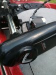
4) I believe its a 24 volt, its a motorguide 6700 pro series. I attached a pic of one that is exactly the same if it helps.
5) From the pedal to where the male plug needs to be is a red and black as far as from the motor to the pedal I would have to unwrap it to see.
I hope that helps clear up what I'm dealing with.
I wish you had started your own thread since you have now confused the folks trying to answer the original posters question. In the future, start your own -- DO NOT jump on someone elsed thread.
I am not going into a long discussion about "why" your boat is wired the way it is. This topic has been discussed to death and you can use the "search" feature to learn about this. But the 12/24 RUN switch position is used when running the motor. The 12/24 CHARGE setting allows charging both batteries from a single output charger through the trolling motor connector. Remember that when batteries are in series they would need to be separated (series connection broken) in order to charge both batteries from a single output charger. The switch does that and places the batteries in parallel.
Now then -- you have two wires coming out of the foot pedal which are the power into the troller. That says you have either a 12 volt or a 24 volt motor. I have not seen every troller on the planet and I'm not going to do your research for you so you need to determine which you have. Since you said it's a 24 volt motor, that's what we will go with. 24 volt motors need two batteries in series to operate properly. Since you have two pairs of wires going to the batteries, you connect one pair of red & black wires to one battery and the other pair of red and black to the other battery. WARNING: You need to make sure the black wire belongs with the red wire in each pair.
THe female connector up front will likely have three or four terminals in it. Since your motor is 24 volt only, only two of those terminals will actually connect to the two wires on the motor. Set the panel switch 12/24 RUN and then using a voltmeter, determine which two terminals have 24 volts. Those are the two terminals in the plug that will be used to power the troller. The IF in this configuration is if there is a four terminal female receptacle you may need a mating plug that has internal jumpers in it. Why??? Because one pair of terminals provides 12 volts, and the other pair of terminals provides 12 volts. The jumper provides the series connection. Remember -- we cannot see your boat so you have some investigation to do. That's why I asked for pictures of the panel (front and back). You cannot guess here unless you want smoke.
Here is what I would do if it were my boat. It eliminates the blasted panel and about half dozen potential points of failure.
1) Ignore one pair of red/black wires at the batteries. Disconnect them and tape them up. DO NOT CUT THEM OFF.
2) Wire the batteries in series as shown in the diagram below.
Note that this diagram shows only two terminals. Your boat probably has four terminals in the female receptacle. That doesn't matter since two will not be used.
3) Connect the red wire via the CB to the POS post of the battery on the right.
4) Connect the black wire to the NEG post of the battery on the left.
5) Fabricate the jumper that goes from the POS post of the battery on the left, to the NEG post of the battery on the right.
6) At the panel up front, use a voltmeter to see which two terminals now have 24 volts on them. Disassemble the plug for the troller and remove any jumpers inside.
7) Connect the red and black wires from the foot pedal to the two terminals in the plug that match the two terminals that showed 24 volts.
8) Go fishing.
I did notice that the troller does not have the connector on the foot pedal cable. You will need one that matches the receptacle on the boat. Remember, you will only be using two terminals. This scheme does not "butcher" the wiring as so many are tempted to do. When/if you sell the boat, put the wiring back so the next owner can take advantage of the 12/24 capability and not have to wonder what you did. Take pictures and make notes and put them where you can find them.