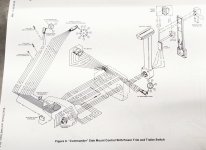
MERCURY CONTROL BOXES

Rpiazza6857

Cadet
Joined
Oct 30, 2020
Messages
26
I am putting a new to me 90hp 3 cyl two stroke on a boat that currently has the same era late 80's early 90's 70hp 3 cyl on it now. I would like to swap the engines but not the control boxes as the wiring runs through the boat. The harness in the boat has the same 8 pin connector however the tilt and trim appears to be different. The tilt and trim wiring that came with the 90 is a harness and plug with spade ends in it, while the harness on the boat has bullet connections for the tilt and trim, is it just a design change and both will work? I have all parts for both harnesses just wondering if they can be interchanged?
 

Chris1956

Supreme Mariner
Joined
Mar 25, 2004
Messages
27,230
The bullet connectors are standard on my '93 Merc. I expect the spade connectors are a "modification". I would replace the spade connectors with bullet connectors.
 

Rpiazza6857

Cadet
Joined
Oct 30, 2020
Messages
26
Both harnesses have not been modified, I have a little more information after working on it a bit last night.

This is a link to the remote in the boat now I am trying to use which came from the 70hp that was on there previous
https://www.nlamarine.com/products/...e-control-shift-box-power-trim-side-mount-90s

And here is a link of the controls currently connected to the motor which are original and work correctly.
https://www.nlamarine.com/products/...n-power-trim-side-mount?variant=7129869549598

The engine side harness I am trying to hook the first remote to is p/n 84-41591A2 unfortunately I cannot read the whole tag for the engine side harness that worked with the second remote on the 70hp, all I can get is 84-41591 and even though the first set of numbers is the same the harness is different. I believe is it a 84-41591A3 but can't be sure. I think I can get the tilt and trim figured out but I am concerned with the 8 pin plug now. The pins do not seem to be in the correct locations to mate with the engine harness. I can see the wire colors and they match, minus 1, one is brown and the other is brown with a blue tracer, seems this will work as wire color codes list the brown with blue tracer is an alternate to brown. I cannot see what pins the wires actually go to however, when I plug them together the wires I can see don't seem to be lining up correctly. They could be twisted in the plug, again not sure. Are all the 8 pins compatible? Does anyone have any experience with this? I would like to use the remote in the boat if possible so I don't have to fish the wires through and the one in the boat looks like all the new aftermarket ones you can buy, if I want to replace in the future it will be easier to do so.
 
Last edited:

BWR1953

Vice Admiral
Joined
Jan 23, 2009
Messages
5,914
Your current control is this one.

Awhile back I saw a guy online in a video who made up some adapters to connect the two types. Maybe you could do something like that.

Commander Side Mount Control.jpg
 

Rpiazza6857

Cadet
Joined
Oct 30, 2020
Messages
26
That is awesome! Looks like it all matches up however digging a little deeper I found these diagrams, two wires are showing to be in different locations than the diagram you have posted there
 

Attachments

  • 38da33d2-f8f3-4fc2-a202-a57b68e56efd_keywire.pdf
    873 KB · Views: 11

Chris1956

Supreme Mariner
Joined
Mar 25, 2004
Messages
27,230
That three prong spade connector looks to fit the external PTT pump/reservoir used on the early PTT equipped motors.

I do not know the last year those were used, maybe mid-80s? After that they went to bullet connectors for the PTT systems installed between the transom clamps.

I presume your motor has one of those PTT systems inside the transom clamps and bullet connectors as well. Normally there would be only 2 PTT (green, blue) wires at the round plug as the power was fed to the PTT switch on a wire that was part of the wiring harness.

If you have the 2 bullet connectors on the motor near the round connector, I would cut off the 3 prong spade connector, add enough wire to match the length of the round plug, if necessary add 2 bullet connectors to the green and blue wires, and tape the PTT wires to the round cable. Some corrugated plastic electrical loom will dress it up if you like. The red wire will need a ring terminal, and be attached to battery power, say at the starter solenoid.
 

Rpiazza6857

Cadet
Joined
Oct 30, 2020
Messages
26
Thank you Chris the control box I am trying to use has the bullet connectors already there for the tilt/trim and I took the jumper off the 70 hp to make the bullets work, Main concern now is the wiring on the 8 pin possibly not lining up.
 

Rpiazza6857

Cadet
Joined
Oct 30, 2020
Messages
26
It looks like by the wiring diagrams the kill wire and the choke wires are backwards on the two plugs, I'm going to check visually in the next day or two.
 

Chris1956

Supreme Mariner
Joined
Mar 25, 2004
Messages
27,230
They did change color, about the time of your motor. Choke went from grey to yellow/black, and charge/tach wire went from brown to grey.

Gee, I think that is correct. You might check. In the early 80's, they tried to standardize the wiring colors. Some years were the old colors, some were the new, some were a mix.
 

Rpiazza6857

Cadet
Joined
Oct 30, 2020
Messages
26
I have to thank everyone for their help on this, I had some time to work on it last night and got everything working, Chris I believe you are correct in saying if it plugs in it will probably work. I ended up going over a few wiring diagrams to realize the wires even though different colors were terminating in the correct spots and were in the correct pin locations. So again you were correct in saying around that era Mercury was messing with wiring colors. There were three discrepancies, choke was now yellow / black tracer on engine side but black / yellow tracer control side. The other was the kill switch, this was black / yellow tracer engine side and yellow / black tracer on control side, so these two were opposite in pins 1 and 6. The final one was brown engine side to brown / blue tracer control side for the overheat warning, this was not a big deal as the wire was listed as an alternate color. Tested all functions and good to go. For the trim to work you need the jumper harness or you would need to make one out of some bullet connectors and eyelets but it is pretty straight forward to remove the old harness and run the blue and green wires to the activator posts on the solenoids. Again thank you all for your help!
 

Chris1956

Supreme Mariner
Joined
Mar 25, 2004
Messages
27,230
I am surprised about the colors of the kill and choke wires on the control side. The new Ign kill wire was always black/yellow. The old wire color was orange or salmon. The new wire color for the choke is yellow/black. The old color was grey. New wire color for starter solenoid is yellow/red. The old color was yellow. Other new wire colors were purple for ign acc and grey for tach signal. I presume these are correct?

The V6 motors got the newer wire colors first, say in 1977. The inline motors followed starting in 1980.

Was the control made by Mercury, or some third party?

I am glad it works.
 

Rpiazza6857

Cadet
Joined
Oct 30, 2020
Messages
26
Attached is the diagram I used to figure it out, both are Mercury quicksilver controls, I circled the wires and then the kill wire
 

Attachments

  • DOC051222.pdf
    95 KB · Views: 6

Chris1956

Supreme Mariner
Joined
Mar 25, 2004
Messages
27,230
Interesting. The first (top) diagram looks to be the expected wiring colors. On the emergency kill switch(as you circled), and you will see black and black/yellow wires.

The second diagram emergency switch has the black and yellow/black wires on it.

Both diagrams look to have the same title, but different numbers on the picture itself. I find it strange that the plugs are compatible, but the wiring colors changed.
 

Chris1956

Supreme Mariner
Joined
Mar 25, 2004
Messages
27,230
Merc did like to make wiring harnesses work for multiple motors. During the 70's Merc was changing from battery powered CDI ignition to ADI. They made sure to have both the power wire and killer wire in the harnesses, so they would work for both types of ignition. So you could replace a 1975 850 (ADI ign) with a 1976 1150 (battery CDI) using the same controls and electrical.
 
Top