Mercury 6.2 ECT DTS Axius Voltage Issue

alldodge

Moderator
Staff member
Joined
Mar 8, 2009
Messages
42,063
The brown color has me thinking it may have gotten hot. Incorrect lube can cause the shift issues
 

tpenfield

Moderator
Staff member
Joined
Jul 18, 2011
Messages
18,040
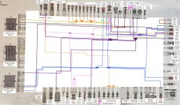
Just looking at my diagram and the newly added purple (ignition) wiring. The things to check look to be:

  • Ignition switch
  • Alternator excite
  • CAN P & H resistors
  • Outdrive Lube
  • J1939 Connector

I'll update as I proceed . . . I appreciate the comments and ideas. :)
 

dubs283

Vice Admiral
Joined
Jul 27, 2005
Messages
5,322
The buzzing of the MPR ONLY happens if I have turned on the ignition for a while , turn it off and then turn that battery switch off. Voltage at the back of the engine then goes from battery voltage down to the 5-7 volt range.
I'm curious as the where the voltage at the back of the engine is being measured with the battery switch off

With the switch off there should be zero voltage provide to the engine except for the clean power (+/-) connection for the pcm, can p/h, and red/blk to the 14 pin which I'm guessing is for a vv display at helm, maybe mercathode. Never got that far into clean power troubleshooting
 

tpenfield

Moderator
Staff member
Joined
Jul 18, 2011
Messages
18,040
Yea, that would go over like a fart in church in my household. :ROFLMAO:
 

tpenfield

Moderator
Staff member
Joined
Jul 18, 2011
Messages
18,040
Thought for the day on the electrical issue . . .

The helm gets its voltage (power) from the house (accessory) battery bank. So, voltage for the engine systems comes from the battery bank, but the key switch ignition voltage comes from the house bank. That might explain how I am (still) getting voltage (5-7 volts) at the main power stud of the engine when I turn the engine battery off.
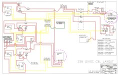
Here is the OEM power schematic . . .
CY-338-Power-Diagram-Original-Markup.jpg
I might swap the ignition keys to see if the problem goes over to the port engine.

Another thought is the ProNautic battery charger, but I have disconnected it from the house bank. Easy enough to test, since there are CB's connecting it to each engine battery.

Trying to figure it out more precisely and avoid the 'parts cannon' . . .
Parts-Cannon.png
 

dubs283

Vice Admiral
Joined
Jul 27, 2005
Messages
5,322
Accy battery does supply power to what appears to be a dc panel first, guessing cabin/house dc main panel which in some cases does have a helm dc breaker switch. However the accy battery is power for the helm/panel switched accessories (blower, bilge pumps, lights, etc) not engine key switches.

Engine key switches get power from the 14 pin harness on the engine. You need power at the engine harness from the engine battery first in order to gain power at the key switches. With the stbd engine battery switch off there should be zero power available at the engine harness, 14 pin harness and subsequently the key switches

The only issue with my keyboard troubleshooting I see is power being supplied to a warning system horn (see, key switch on but main engine battery off, this was part of a thread dodge had earlier). I'm not sure where the power supply for that warning horn is coming from nor how the system knows the key switch is in the "on" position

Getting back to my previous post about clean power one other thought is the 14 pin red/blk pin having constant power could be for this warning system or it could be for helm/ccm clean power or maybe both?

I really do feel your issue stems from either an issue with the stbd engine battery switch/wiring or something with your recent alternator r and r. In any case you need to start at the stbd engine battery and work your way towards the engine. Isolation of components is key in locating the source
 

tpenfield

Moderator
Staff member
Joined
Jul 18, 2011
Messages
18,040
It is starting to rain, so I may not get much testing done today . . . I did get the starboard outdrive finished in the early morning hours.

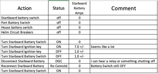
I did some testing with my amp meter (DVM)

Here are the results . . .
Screenshot 2024-06-06 at 9.24.45 AM.png
.
It seems that something is getting turned on when the ignition switch is turned on, and it stays on even when the ignition switch AND the battery switch are turned off. Disconnecting the battery entirely resets it.

I'll be tracing wires from the battery switch and the isolation post . . .

Stay tuned and thank you all for the continued assistance. ☺️
 

Scott Danforth

Grumpy Vintage Moderator still playing with boats
Staff member
Joined
Jul 23, 2011
Messages
49,566
key on will initiate the ECM, the fuel pumps will prime the system.

unplug the fuel pumps and see if that drops your load
 

tpenfield

Moderator
Staff member
Joined
Jul 18, 2011
Messages
18,040
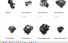
This may be a solution, Just came on the market in NY. Just need to keep saving my allowance :ROFLMAO:

Screenshot 2024-06-06 at 9.38.03 AM.png

BTW - I just checked the Mercury website and the 6.2L sterndrive is not listed . . .:unsure: can't say I blame them at this point. :ROFLMAO:
 

Scott Danforth

Grumpy Vintage Moderator still playing with boats
Staff member
Joined
Jul 23, 2011
Messages
49,566
BTW - I just checked the Mercury website and the 6.2L sterndrive is not listed . . .:unsure: can't say I blame them at this point. :ROFLMAO:
you gotta think like the brunswick marketing team.

the motors are still there


1717686667703.png
 

muc

"Retired" Association of Marine Technicians...
Joined
Jul 7, 2004
Messages
2,144
Diverting back on topic . . . I have mapped the power wires (as best I could) from the overly busy wiring diagram.

Not sure it will upload properly, but here it is . . . I took some liberties with the color designation, since my graphic software doesn't know about wire stripes. :D
.
View attachment 399087
.
I believe that I found an error in the diagram reference in the area of the coil packs, so I'm not sure if the #45 item is the 'Throttle Demand' or not. The manual has one of the coil packs referenced as the throttle demand . . .

Anyway, I'll be going through this over the next few days, but I did want to post it for those that may see something. I assume the the VesselView and OBD-M (Diacom) readouts are coming from the connections at PCM-A and PCM-C . . . not sure which one(s) relate to 'system voltage' and 'battery voltage' on the Diacom screen.
Looking at this. I believe #45 is port exhaust temp, #46 is lube bottle, #47 is DLC, #48 is O2 heaters. But I can't be sure, so ----
Can you post or PM me the compete original diagrams? I don't have access to your engine wiring diagrams.

I saw a picture of a circuit breaker for clean power that looked pretty bad. Clean power is critical for these systems. Both the positive and negative clean power need a voltage drop free connection to the engine battery for the engine that PCM is mounted to. We had boat come back to the dealership that had been winterized, stored and summerized by by another shop it had all sorts of weird issue, many fault codes, no steering on port and couldn't shut if off unless you turned both keys off at exactly the same time. problem ended up being that when the boat was summerized the other shop had switched the clean power grounds. Had port clean power connected to starboard battery and stbd clean power connected to port batt. That was all that was wrong, once we swapped them every problem went away -- now this was a Volvo powered boat but Volvo and Merc are pretty close in how this stuff works. Clean power is named that because perfectly clean power is needed.

I saw mentioned that it's possible one of your warning horns is connected to house battery power? If so this must be corrected. Each engine (and when I say engine I mean engine all the way to the dash -- gauges, throttles, command module, thrust vector module. basically anything MerCruiser) must only receive power from that engine's battery. ONLY.

MY best guess is you have a clean power issue or an interconnect --- MerCruiser powering something it shouldn't or being powered by something it shouldn't. And when I power, I mean power and ground, both are important.

If this boat was brought to me. First thing I would grab is cutters and a big bundle of tie wraps, a roll of electrical tape and a big pack of alcohol wipes to clean the black sticky from my hands. Unfortunately I think this boat might have come from the factory miss wired or something got changed during rigging/additions. And these problems are starting to show up more and more as age and voltage drop increase.

If you have the Cruisers wiring diagram for the helm, it would be nice to look at.

One other thing I noticed. It looks like Cruisers is using a battery isolator so the engines can charge the house batteries. I seem to remember some talk about isolators needing to be approved by Mercury in DTS applications. Something about too much voltage drop across the isolators. But I didn't pay to much attention because all our boats had transitioned to VSRs by then. Maybe someone else remembers something about this?
 

alldodge

Moderator
Staff member
Joined
Mar 8, 2009
Messages
42,063
It looks like Cruisers is using a battery isolator so the engines can charge the house batteries. I seem to remember some talk about isolators needing to be approved by Mercury in DTS applications
Would be interesting to find out, Chap also used a isolator on my OB's
 

Scott Danforth

Grumpy Vintage Moderator still playing with boats
Staff member
Joined
Jul 23, 2011
Messages
49,566
battery isolators are simply glorified diode banks and the battery will see a 0.7volt drop across the isolator.
 

bruceb58

Supreme Mariner
Joined
Mar 5, 2006
Messages
30,537
I have a 2017 6.2L but it's the newer Mercruiser developed engine(Not a GM). It does however still use the GM PCM if I am not mistaken.

On my engine, there is a separate power harness that goes directly to the battery because it wants 12V ALL THE TIME. It's also going straight to the battery to eliminate voltage drop to the PCM, FI and ignition during cranking. I wonder if that's your issue.

Apologize if this was already mentioned earlier in the thread.
 

tpenfield

Moderator
Staff member
Joined
Jul 18, 2011
Messages
18,040
Yes, this engine (2016) is the in-house Mercury built (Not GM), It has the PCM 112 control module.

Here is an updated power diagram and some voltage readings that I took.

I agree voltage is getting somewhere it shouldn't.
.
Power wiring diagram, as best I can make ( @muc ) I will PM you the full diagram (big file)
.
Electrical-Diagram-Merc62-DTS-WC3.jpg
.
Here are the voltages that I recorded while going through a sequence.
Batt Switch OFF, -> then truned Batt Switch ON, -> Then Ignition ON (not running), -> Then Ignition OFF, - >Then Batt Switch OFF, -> Then 20 mins +/- later with Batt Switch still off.
.
Screenshot 2024-06-06 at 4.30.24 PM.png
.
Battery voltage was 13.1 during the test sequence

When the battery switch is turned off AFTER the Ignition has been on (and then turned off) the voltage on the red/purple goes UP from 5.5 to about 7.2 within 30 seconds to a minute. At the same time the voltage on Red/Blu, Red/Wht, Red Org go from 0.8 down to 0.0.

I'm going to be looking at some wiring in the starboard electrical box. . . .

Thanks for any insight, ideas, comments.
 

tpenfield

Moderator
Staff member
Joined
Jul 18, 2011
Messages
18,040
Quick Update . . .

After 1 hour I am seeing 11.9 v on the Red/Purple & Red/Pink wires . . . If I disconnect the starboard battery, I am still seeing 11.9v on those wires.

Sort of means the engine is getting some power from another place.

As for now it is beer o'clock . . . more 'fun' in the AM.
 

tpenfield

Moderator
Staff member
Joined
Jul 18, 2011
Messages
18,040
question for the Merc experts among us . . . I still consider myself a journeyman status . . . Does the smartcraft/DTS have/need a keep alive connection?

Or . . . if/ when I shut the battery off, should there be no power to the engine systems? (asking for a friend :ROFLMAO: )
 

alldodge

Moderator
Staff member
Joined
Mar 8, 2009
Messages
42,063
question for the Merc experts among us . . . I still consider myself a journeyman status . . . Does the smartcraft/DTS have/need a keep alive connection?

Or . . . if/ when I shut the battery off, should there be no power to the engine systems? (asking for a friend :ROFLMAO: )
No expert by any means but remember my issue?
I turned switches OFF and smartcraft would not power off until I disconnected clean power. I'm sure there is more then just that, but it would not power down prior
 
Top