Manual/Auto Aerator Switch

Status
Not open for further replies.
Joined
Jun 9, 2007
Messages
12
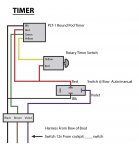
Next questions will be the timer, timer control rotary switch and manual/auto Aerator switch all in the bow control panel. The round pod timer have 4-terminal red, black, green and yellow is normally loop but mines is not, 1 yellow wire goes to rotary switch, 1 red wire goes to rotary switch then to switch at bow, 1 green wire goes to brown wire of harness from boat, Black wire goes to Black of wire harness and switch at bow, Also I have a violet wire coming from harness from boat going to switch at bow, the switch at bow was busted up in pieces so I have one to replace it with (Its used). I think this is the way it supposes to connect up, here is a hand drawing of what I type, maybe someone can understand it any info will help and thanks for reading my post.
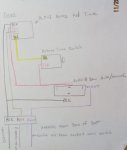
Bow Aerator Timer Diagram 2.JPG
 

Don S

Honorary Moderator Emeritus
Joined
Aug 31, 2004
Messages
62,321
Re: Manual/auto Aerator switch

Re: Manual/auto Aerator switch

Where does the pump attach?
Where do you pick up 12V power and ground from the boats electrical system?
That switch@ bow, do the red and black terminals both go on that switch? Seems odd. Thats probably the one thing that is most confusing with it.
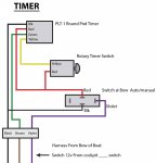
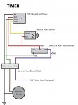
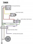
I also redrew the picture to make it a little easier to see. Couldn't read one of the words in the last sentence.

Timer.jpg
 
Joined
Jun 9, 2007
Messages
12
Re: Manual/auto Aerator switch

Re: Manual/auto Aerator switch

Thanks Don S. For the Redrawging and Info.
The Aerator pump get attached from Bow harness (Brown), The Brown, Black and Violet is the boat side of harness, The pump (Brown) is connected to Green from Timer, The(Black,Ground) is connected to Black from Timer and Switch at bow, The (Violet) is connected to switch at bow, Now the Violet gets 12v when the switch in cockpit console is turn ON (Name Aerator 1).

If you Look at the drawing Below you could see what i was referring to.

The switch in bow panel is a 3-way(On-Off-On).
The Boat had some theft while it was in storage, the rear deck where the Batties and charger was and Bow area was the bow switches and Trolling Motor where snatch out and Not taking off (Dumb Thieves).
And I`m still looking for Operators/Brochures Manual On 99` Charger 375T Fish & Ski, So any info will Help.

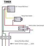
Timer.jpg
 
Last edited:

Don S

Honorary Moderator Emeritus
Joined
Aug 31, 2004
Messages
62,321
Re: Manual/Auto Aerator Switch

What you are saying, and what you are drawing makes no sense.
Need specifics not just wire color.
Which wire is hooked to ground?
Which wire is hooked to incoming power?
What does the purple wire connect to?

Your toggle switch at bow 3-way(On-Off-On) can not be wired like that. Never seen a switch with 4 pins in that configuration before.
A picture or a better drawing that shows the connections, and their layout would help in figuring out how it all works. Does the switch have a light in the toggle? That would be the only thing a switch would have a black wire on it for.

Does the pump hook to the brown and black wires at the bottom of the drawing?
Does the purple wire supply 12V to the system?
 
Joined
Jun 9, 2007
Messages
12
Re: Manual/Auto Aerator Switch

Black=Ground
Violet=12V
The Violet wire gets 12v from switch at main console when turn on
Yes have two lights on 3-way Rocker switch (NOT Toggle)
The Rocker Switch Have 4-terminals on back thats why I put it on the drawing, Same as the one the thieft broke, I just ues one from the main console that had the lights on it.
At the bottom of drawgs is the Connector/harness
Black goes to Black=Ground
Brown goes to Green=To Pump(Brown)
Violet goes to Switch at bow.

Timer.jpg
 

Don S

Honorary Moderator Emeritus
Joined
Aug 31, 2004
Messages
62,321
Re: Manual/Auto Aerator Switch

I'm doing some assuming here, because what you are saying and drawing isn't making any sense.
Below is the new drawing. Assuming the wires are as you drew them, and that the violet wire is the main power for the whole system, then it has to be like this.

timer setup.jpg

Here is the problem with this setup. You have no wiring to manually operate the pump. The violet wire from the main connection is going to a load terminal of the switch, and the center terminal of the switch where power should be coming in is now feeding power to both timers. Why do you have 2 timers. Timer 2 powers timer one, and timer one can also work by itself. Makes no sense.

It may be that timer one doesn't work, and timer 2 is doing all the timing, and the manual use of the switch is never used.
 
Joined
Feb 17, 2012
Messages
2,906
Re: Manual/Auto Aerator Switch

from the drawing it makes sense that the pump could be used in auto but i can not see a way that the switch will work in manual unless it was not a on/off/on switch in the first place.
I am kinda intrested if the rotary timer switch is a timer or a selector switch that controls the timer.

any details or wiring diagrams on the components would realy help.


me and don are on the same page ....... i go with what he says as he posted faster than me
 
Joined
Feb 17, 2012
Messages
2,906
Re: Manual/Auto Aerator Switch

don i can not find a print on the timer but i have noticed that the yellow is normally looped so im wondering if this can be cut and add resistance to change the off timer parameter thus the rotary timer is in fact a selector switch that is adding resistance to the yellow wire and changing the off timer. if this was the case then manual may well be on the rotary switch thus no need for it to be on the on/off/on switch
 
Joined
Jun 9, 2007
Messages
12
Re: Manual/Auto Aerator Switch

Hi Guys Thanks for all your help, I will connect it up this way cause I have know ideal, cause all wires was ripe out (not cut) so I match up the wires as they was parted away, I thought I was detailing the drawings as I speak (typing the words), Also my second post I was thinking how it may have been connected, I also use a VOM and test light to find ground and whats get 12v when switch, Cause the wiring diagram from charger boats did not make any sense or show rotary switch.
 

Don S

Honorary Moderator Emeritus
Joined
Aug 31, 2004
Messages
62,321
Re: Manual/Auto Aerator Switch

I think I now understand the system, below is how to rewire the switch to make it manual and automatic.

The reason for the rotary switch (2 in the drawing below) is to make the timer adjustable. Number 1 switch is non adjustable and works at one cycle speed, the #2 rotary switch can vary the cycle times.

If that is the case, and you would also like to make it work manually as well, all you have to do is rewire the switch as shown in the picture below.
Add a single green wire to one end terminal and splice it to the other green wire for manual. Put the red wire on the other end terminal of the switch, and the purple wire to the center terminal of the switch.

new wiring.jpg

As far as that manual/auto switch goes, it's probably layed out for 6 or 8 terminals on the back, but only 4 used. The manufacturers only make one basic switch, the insides and number of terminals is changed for the type switch.

Here is one I found from Sierra as an example. The layout may change between manufacturers, you will need to determine how yours is layed out.

SPDT switch.jpg
 
Status
Not open for further replies.
Top