M40D2 water system question

LukeFishWalker

Petty Officer 3rd Class
Joined
Jul 23, 2015
Messages
95
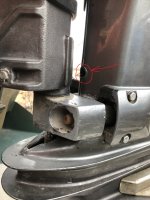
I am getting an unusual amount of water coming from the hole in the mid section shown IMG_0342.JPGin the picture and low water pressure from the tattle tail. I had ran through some shallow water and I assumed that I had picked up something so I got towed back to the launch. When I got home I pulled the lower unit and inspected the pump, the impeller was fine but I had a spare and used it. The metal cup & plate was fine so I left it. I then pulled the thermostat and found signs of vegetation and very small corrosion. So I had a damaged washing machine hose and stuck it on the pipe and ran water through it. Is it possible that I disconnected the pipe from the engine base leading into the block? and if so, can I tap it back into place or do I need to pull the powerhead?
Thank You For Your Time & Patience,
LukusIMG_0342.JPG
 

Sea Rider

Supreme Mariner
Joined
Sep 20, 2008
Messages
12,345
Impossible for the water pipe to unlock itself where attaches to the lower crankcase. You mean the large orifice located right behind the middle section side of the tell tale (water discharge indicator). The amount of water will vary depending if the thermo opens or closes more specially at speed. Place your palm there and check if the exiting water temp varies or not. If it does, the thermo is good to go, if at a constant temp whether hot or cold the thermo is shot, install a new one in.

Happy Boating
 

LukeFishWalker

Petty Officer 3rd Class
Joined
Jul 23, 2015
Messages
95
Thank You Sea Rider for responding.
The picture above is a small hole in the casting of the mid section on the front and just above the lower engine mount. The compartment that the water appears to be coming from is where the gear shift runs vertically and also where the water pump is on the foot.
I used to see a pretty good stream out of the tattle tail ( Exhaust Manifold ) and after this incident the stream is reduced.
After looking at a parts diagram I see that I do not have the Water Pipe Rubber Lock Part# 346652040 that appears to seal the to the pipe flange and the top of the Rubber Water Pump Seal that actually attaches to the water pump housing.
I took the Rubber Water Pump Seal and put it on the pipe and there is a little slack. So I am going to get the rubber piece that goes between it and try that. I will report back
 

LukeFishWalker

Petty Officer 3rd Class
Joined
Jul 23, 2015
Messages
95
I added the Water Pipe Rubber Lock and there was no difference.
I am now going to replace the Upper Case and a complete water pump kit.
I am now guessing that the source of the water is coming from where the Upper Case goes over the driveshaft.
I will report back
 

Sea Rider

Supreme Mariner
Joined
Sep 20, 2008
Messages
12,345
So far can't interpret the fisrt pic, too close-up shot.. Before going for a new upper case and complete water pump kit, with removed lower leg sitting in a container filled with sufficient water level to cover both water intake screens, install a drill machine on upper drive shaft splines make it spin CW and check if the water pump is pumping right along good water pressure.

If good, lock with finger the rubber seal located on top of the case and check if there's water coming from where the upper case meets the drive shaft while the drill is spinning same. Aside from this seal there's 3 more parts associated to the water pump, probably one is missing ? Chaeck..

Happy Boating
 

LukeFishWalker

Petty Officer 3rd Class
Joined
Jul 23, 2015
Messages
95
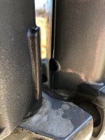
The hole I am trying to describe is on the mid section casting where the 2 halves are fused, just above the lower motor mounts. This picture might be easier to understandTohatsu Midsection.JPG
 

Sea Rider

Supreme Mariner
Joined
Sep 20, 2008
Messages
12,345
Orifices built on Tohatsu's lower legs are usually water drain ports, seeing an abnormal amount of water compared to previous amount happened when running the motor on muffs ? Is there any other water drain orifice besides the mentioned one located on the lower leg ? If there's a good flow of water exitng through the prop and water indicator and motor cooling right would't worry too much...

Happy Boating
 

LukeFishWalker

Petty Officer 3rd Class
Joined
Jul 23, 2015
Messages
95
I did as you suggested by using a piece of rubber hose pushed onto the driveshaft and using a drill bit with duct tape holding the drill bit. Then using a high speed drill on the drill bit I turned the driveshaft CW with the lower unit submerged in water. Most of the pressure generated by the impeller was escaping through the driveshaft hole and even more when attempting to determine if the actual water outlet hole would hold head pressure. There is a very small hole on the pressure side in the Lower Pump Case that does expel a great deal of pressure horizontally, but the water loss is minimal and I assume it's designed as a pressure relief mechanism. I also noticed that the driveshaft isn't absolutely perfectly centered in the Upper Pump Housing.

When I put the hose directly on the pipe ( Water Pressure Pipe Leading Into The Block ) and turn on the hose ( About 5lbs Of Pressure ) there is sufficient water flow to mimic how the tattle tail used to function.
Thank You For Your Time & Patience,
Lukus
 

Sea Rider

Supreme Mariner
Joined
Sep 20, 2008
Messages
12,345
Can you post a pic of the water pump case showing the mentioned orifice. Have never disassembled a 40 HP to see what its water pump looks like. Does the upper pump's case where the drive shaft passes by has a built in rubber seal, whatever adjacent to the drive shaft ? does the drive shaft has signs of wear right where it passes through the case ?

The case is non adjustable, seats firmly down onto a fixed resting position and bolts directly to the lower leg , strange that the drive shaft it's not well centered in the upper case.

Happy Boating
 

LukeFishWalker

Petty Officer 3rd Class
Joined
Jul 23, 2015
Messages
95
There is no " Seal " where the driveshaft goes through the upper housing.
I am now hunting down a new upper pump case and water pump kit.
It seems that there are a huge amount of parts from Japan that are on back order and these 2 items that have been superseded by new part numbers are in scarce supply.
The upper pump case 3C8560161 is superseded by 3T5650160.
The Pump kit 3C8873221 is superseded by 3T5873222.
And the old parts will not interchange with the new parts.
 

pvanv

Admiral
Joined
Apr 20, 2008
Messages
6,509
The original kit is still available.
3C8873223M​
WATER PUMP REPAIR KIT​
$66.43​
Available​

But the upper housing requires the newer parts:
3T5650160M​
UPPER PUMP CASE​
$30.68​
/*MUST USE WITH 3T5873223M W/P KIT OR 3T5 PARTS*/
 

Sea Rider

Supreme Mariner
Joined
Sep 20, 2008
Messages
12,345
Paul,

Just to know, by upper housing you mean the existing old one or it's a different newer model ? Which newer parts will that be, the ones located right above the housing mentioned in the part's schematic diagram numbers 29-31-32-33 ?

Happy Boating
 

LukeFishWalker

Petty Officer 3rd Class
Joined
Jul 23, 2015
Messages
95
Paul, Thank You For Correcting my previous statement.
The parts may not yet be superseded by the new numbers.
The 1992 - 2002 NS & M 40/50 and a few other later 2 stroke
models use the 3C8873221 pump kit & 3C8560161 housing.
However, the 3T5873222 pump kit & 3T5650160 housing
are factory parts for the some of the TLDI models and do
in fact work on the carburetor M models. And some local
mechanics prefer to use the T parts because of the
improvements made to the cup, upper housing and one of the gaskets.
The parts are set to arrive Friday and I will post my results,
Thank You For Your Time & Patience,
Lukus
 

LukeFishWalker

Petty Officer 3rd Class
Joined
Jul 23, 2015
Messages
95
The parts came in and before I put them on I ran the 3/16 hose through the lower pump housing all the way to the screen(s) and no obstruction. Then I installed the new upper housing ( 3T5650160 ) and the new pump kit ( 3T5873222 ). But before I put the lower unit back on - I used the same piece of rubber hose and my drill to test the assembly in my old ice chest. Once again with enough water to cover the screen(s) and spun it Clock Wise.
There was no difference with these new parts.
The pressure generated by the pump still comes out the driveshaft hole and not a whole lot of head pressure from the water pump upper housing outlet.
 

Sea Rider

Supreme Mariner
Joined
Sep 20, 2008
Messages
12,345
By drive shaft's hole, you mean the one located on top the water pump housing where the shaft passes by located next to the black rubber grommet where the upper tube connects to, right ?

Was checking a 2 stroke Tohatsu M50 which is the older brother to the M40 and there's no such hole circled in red seen in post 6. Don't have the slight idea what's that hole for ? Seems the new production line has eliminated such hole...

Happy Boating
 

LukeFishWalker

Petty Officer 3rd Class
Joined
Jul 23, 2015
Messages
95
This old frame is the 1993 25 Mega which is the carburetor'd de-tuned 40 for the 25 HP restrictions back in the day. The hole in the picture above emits almost half of what the pump puts out. Now that I put it on the water ( Ran it ) and then came home and did the trick with the rubber hose & drill, there is a lot less water coming out this drive shaft hole which goes through the upper water pump housing ( Plastic housing that contains the metal cup for the impeller ) . Now I am heating up some water to check if the thermostat opens.
Edit:
The thermostat started to open around 95 and was fully open by 115
 
Last edited:

Sea Rider

Supreme Mariner
Joined
Sep 20, 2008
Messages
12,345
This old frame is the 1993 25 Mega which is the carburetor'd de-tuned 40 for the 25 HP restrictions back in the day. The hole in the picture above emits almost half of what the pump puts out. Now that I put it on the water ( Ran it ) and then came home and did the trick with the rubber hose & drill, there is a lot less water coming out this drive shaft hole which goes through the upper water pump housing ( Plastic housing that contains the metal cup for the impeller ) . Now I am heating up some water to check if the thermostat opens.
Thermo just cools the motor to work inside it's heat range, if doesn't open will have an overheat condition. With removed thermo and cup bolted on connect a water hose righ on the lower water tube, open the water faucett and check what happens. Is water coming nicely out the "hole", through the prop and water indicator at same time (peeing port)

Happy Boating
 

LukeFishWalker

Petty Officer 3rd Class
Joined
Jul 23, 2015
Messages
95
Yes, there is sufficient water when I connect the hose directly to the supply tube and there is little to no resistance if I blow in the hose. However, when I ran it after about 10 minutes up the river I pulled the cowl and the head felt warmer than normal. I just wanted to eliminate the thermostat. I believe it's the inadequate supply at the pump that's causing the slightly warmer than normal temperature.
 

pvanv

Admiral
Joined
Apr 20, 2008
Messages
6,509
You should have the stat installed. Use an IR thermometer to check temps.
 

Sea Rider

Supreme Mariner
Joined
Sep 20, 2008
Messages
12,345
The motor has always been used in river for extended years of usage ? If thermo it's working right and seems to be slightly overheating probably needs a full powerhead water passages clean out. River water surely contains lots of contaminants that could already have adhered to all the water passages and motor not disipating fast current powerhead's internal temp as it should.

Can run any motor without a thermo but will never achieve it's correct working temp, take too long while working too cold, will carbon up the spark plugs, combustion chambers, increase fuel consumption and wear the motor faster. The motor came factory installed with a thermo for some reason, keep using one.

Happy Boating

 
Last edited:
Top