Low voltage to fuel pump relay

Leedanger

Petty Officer 1st Class
Joined
May 29, 2011
Messages
323
Volvo Penta 5.7 GSi PWTR
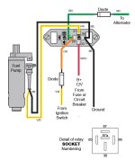
Hi everyone. Having intermittent issues with the fuel pump. New fuel pump, filters, pick up, anti syphon, relay, and fuel line. I’m getting 12v on the battery wire at the relay (30), but with the ignition on I’m only getting 1V to (85) IGN/Alternator. I guess I’m a little unclear about how that receives its full 12v being it has two wires going to one location you’d think if one failed the other would pick up the slack, but even while cranking voltage doesn’t change. Looks like there are diodes on each wire somewhere. Are those potentially my culprit and if so do I need to just start unwrapping the wire loom to locate? Seems like there is an easier way to resolve this but my brain seemingly also has wiring issues and shut down on me.

Thanks!
 

bruceb58

Supreme Mariner
Joined
Mar 5, 2006
Messages
30,537
It will receive 12V to the relay coil while cranking(through diode from starting circuit) and then once the engine starts, it will get 12V from the alternator, also through a diode to that coil.
 

Attachments

  • volvo_fuel_pump_relay.jpg
    volvo_fuel_pump_relay.jpg
    85.7 KB · Views: 12

Scott Danforth

Grumpy Vintage Moderator still playing with boats
Staff member
Joined
Jul 23, 2011
Messages
49,534
To get an 11 volt drop on a diode means you have a bad connection upstream
 

kingsfisherman

Petty Officer 2nd Class
Joined
Feb 22, 2006
Messages
105
Volvo Penta 5.7 GSi PWTR
Hi everyone. Having intermittent issues with the fuel pump. New fuel pump, filters, pick up, anti syphon, relay, and fuel line. I’m getting 12v on the battery wire at the relay (30), but with the ignition on I’m only getting 1V to (85) IGN/Alternator. I guess I’m a little unclear about how that receives its full 12v being it has two wires going to one location you’d think if one failed the other would pick up the slack, but even while cranking voltage doesn’t change. Looks like there are diodes on each wire somewhere. Are those potentially my culprit and if so do I need to just start unwrapping the wire loom to locate? Seems like there is an easier way to resolve this but my brain seemingly also has wiring issues and shut down on me.

Thanks!
"but with the ignition on I’m only getting 1V to (85) IGN/Alternator"
is this when in start mode? I thought they came on for 2 secondsv in start mode.
 

cobalt1999

Petty Officer 2nd Class
Joined
Apr 28, 2010
Messages
102
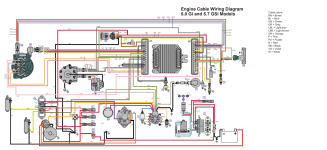
I think the wiring diagram that Bruce58 posted is for a carbureted motor, it would have one pump. The OP Leedanger stated they have the 5.7 GSi PWTR, which would have the fuel injected TBI system with the two pumps.
The ECM controls the pumps, I believe the relay should have constant 12v.
 

QBhoy

Fleet Admiral
Joined
Mar 10, 2016
Messages
8,342
You might find that you may just be chasing rainbows with the 1volt reading there. May just find that you have 1v there residual with nothing powered up. Just thought I’d mention it. You checked the basics and usual obvious things…like wiring around the ignition system or kill/safety wiring network ?
 

Leedanger

Petty Officer 1st Class
Joined
May 29, 2011
Messages
323
Thanks everyone. The mistake I was making was believing I should be getting 12v with the key in the on position when the engine isn’t running. Makes sense that it only gets 12v while cranking until the alternator takes over, especially since this engine isn’t equipped with an oil pressure switch.
I haven’t had a chance to circle back to it but this does help thank you!
 

kingsfisherman

Petty Officer 2nd Class
Joined
Feb 22, 2006
Messages
105
Thanks everyone. The mistake I was making was believing I should be getting 12v with the key in the on position when the engine isn’t running. Makes sense that it only gets 12v while cranking until the alternator takes over, especially since this engine isn’t equipped with an oil pressure switch.
I haven’t had a chance to circle back to it but this does help thank you!
"especially since this engine isn’t equipped with an oil pressure switch."

have you looked on the port side of the block just above the oil filter mounting location for one?
 

Leedanger

Petty Officer 1st Class
Joined
May 29, 2011
Messages
323
I think the wiring diagram that Bruce58 posted is for a carbureted motor, it would have one pump. The OP Leedanger stated they have the 5.7 GSi PWTR, which would have the fuel injected TBI system with the two pumps.
The ECM controls the pumps, I believe the relay should have constant 12v.
It’s not TBI it is in fact carbureted. I double checked the model number and what I posted it right.
 

Leedanger

Petty Officer 1st Class
Joined
May 29, 2011
Messages
323
"especially since this engine isn’t equipped with an oil pressure switch."

have you looked on the port side of the block just above the oil filter mounting location for one?
Yessir. I’m surprised myself not to find one. I was under the impression they were mandatory for all marine platforms where an electric fuel pump is used. But definitely not one just above the oil filter where you’d normally see it like you said nor on the top of the block in the back next to the coil. 🤷🏻‍♂️
It does have the oil sending unit just above the oil filter but no switch.
 

Leedanger

Petty Officer 1st Class
Joined
May 29, 2011
Messages
323
You might find that you may just be chasing rainbows with the 1volt reading there. May just find that you have 1v there residual with nothing powered up. Just thought I’d mention it. You checked the basics and usual obvious things…like wiring around the ignition system or kill/safety wiring network ?
Yessir thank you. Diving back into it today. I appreciate all the responses.
 

kingsfisherman

Petty Officer 2nd Class
Joined
Feb 22, 2006
Messages
105
Yessir. I’m surprised myself not to find one. I was under the impression they were mandatory for all marine platforms where an electric fuel pump is used. But definitely not one just above the oil filter where you’d normally see it like you said nor on the top of the block in the back next to the coil. 🤷🏻‍♂️
It does have the oil sending unit just above the oil filter but no switch.
I guess it doesn't have the S.L.O.W. mode option
 

Leedanger

Petty Officer 1st Class
Joined
May 29, 2011
Messages
323
so it's a GS not a GSi?
🤦🏻 Holy hell do I have a thick skull sometimes. I looked at that number 3 different times and each time I read an i at the end. Took a picture and still read an i. Glad you all are smarter then my dyslexia..my mistake. Confirmed a GS. Not for nothing tho I learned something new about model numbers today so there’s that.
 

Leedanger

Petty Officer 1st Class
Joined
May 29, 2011
Messages
323
It did end up being the diode on the cranking circuit but I replaced both for good measure. Thanks to everyone that chimed in, I always end up learning something new. Posted a video explaining how I understand the system and what I did to repair it if anyone is interested or might find it useful. Cheers
 
Top