LED Driver question

alldodge

Moderator
Staff member
Joined
Mar 8, 2009
Messages
40,718
Have two 13.5V LED light with magnifying lens. Came with a 13.5V 3000mA and called a LED driver. The "driver" burned out and figured it out by using voltmeter and swapping with other working light.

Bought a 13.5V 1A power supply. When plugged in the light flashes ON/OFF and not real fast, maybe once a second or so.

This is when I noticed the original said LED driver. Read up that some LEDs require a constant current and not constant voltage. So what is the issue(s)?
 

bwkre

Petty Officer 2nd Class
Joined
Jul 11, 2010
Messages
177
3000mA is 3A. So it appears that your power supply is under rated and shutting down then restarting. That's why they blink. LED's require a constant current source, and you appear to have purchased a constant voltage source, commonly known as a power supply. Not the proper supply.
So you need to find a constant current source capable of delivering 3000mA, then it must be able to produce 13.5v.
Something like this should work, Google it

MEAN WELL LPF-60-20​


It is 120vac input
constant 3000mA output, 12 to 20vdc
Max power is 60w, so your 13.5v x 3000mA=40.5W well within this units range.
Should work just fine
 

bwkre

Petty Officer 2nd Class
Joined
Jul 11, 2010
Messages
177
OK,
you stated that you have two 13.5v LED lights, were they powered by the same driver? If so how were they connected, in series?
Is there a part # on the old driver?
 

alldodge

Moderator
Staff member
Joined
Mar 8, 2009
Messages
40,718
I'm not taking the light apart to see how its wired. It has voltage and amperage previously listed. I can go to Ottlite and get the same led driver (with part number), but want one which might be made better and last longer.

Read up that some LEDs require a constant current and not constant voltage. So what is the issue(s)?

Assuming I do need a 300mA led driver and not a power supply
 

sam am I

Commander
Joined
Jun 26, 2013
Messages
2,169
So what is the issue(s)?
You asked..........

I believe the blinking is being caused by a over current protect circuit in either the lamp's remaining other circuitry or the P.S. itself because the current isn't being limited with your replacement P.S., hence to limit current.......

If you use a power supply that is your typical regulated voltage 13.5V @ 1A (a constant voltage source), you have 2 options (off the top of my head) to re-design this C.V. P.S. to work for the lamp that have LED's configured (a bunch-o LED wired in series and/or parallel) to run from a "LED driver" (constant current source).

And BTW, LED's don't always "require a C.C. source to work", they can work with both C.V. source or a C.C.. source, but most designs today where the config's are stacking many LED's in series/parallel are using C.C. sources because LED's can run more efficient and max'd out with a C.C. source, BUT you certainly can design to make them work with either...........

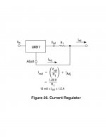
1) Add a transistor (or LM317 set at 300mA, see below) configured as a C.C. source to the output of your 13.5V @ 1A C.V. source.

2) Limit and set the LED's If(LED's forward current) with a resistor, BUT you have to find the total Vf(LED's forward voltage) of the circuit 's LED's combination. (data sheets and circuit config).

e.g. Vf(total) = 7V and you want to run the LED's @ 300mA then (13.5V - 7V)/300mA = 21.6 ohms (wattage = I^2 * R = 2W)

LM317_D-2314752.jpg
 
Last edited:

alldodge

Moderator
Staff member
Joined
Mar 8, 2009
Messages
40,718
Well I guess that's my answer. Hmmm
I was thinking of putting a 450 ohm resistor inline with just the hot side. Seeing what I'm missing guess that won't work

13.5/.0300 = 450 ohms

Shows how much I don't know
Thanks

Oh and their are 30 LED's probably series/parallel
Its an Ottlite
 

sam am I

Commander
Joined
Jun 26, 2013
Messages
2,169
Sure and yeah w C.V. and limiting current with diodes(small sig, zener, LED, tunnel, yada yada) Vf/Vz junctions, the total Vf of the LED(s) is just "used up" if you will and the left over(excess) voltage then sets the total circuit current,

It = (Vt - Vf)/R

Solve for R @ 300mA and assume Vf total is 7V, then

(13.5 - 7V)/300mA = R

21.67 = R

We all know just enough to get in trouble with how much we actually never knew........lol
20210929_115844.jpg
 
Last edited:

sam am I

Commander
Joined
Jun 26, 2013
Messages
2,169
No, the 22 ohm is a series limiting resistor to use just with your 13.5V P.S. as a C.V. source, BUT I guessed at the 7V Vf

Use a 317 with your 13.5V P.S. as depicted above as Vin in #6 as a C.C. source on it's output, use the formula they provided for R1 and wire as they'll shown, I never calculated that value.
 

alldodge

Moderator
Staff member
Joined
Mar 8, 2009
Messages
40,718
Probably easier to place a meter inline to measure current with the transistor and a pot. Adjust pot until get the proper current then replace with fixed

Mostly because I don't know what diodes are used nor how they are wired
 

sam am I

Commander
Joined
Jun 26, 2013
Messages
2,169
Right, black box it! And many ways to skin this cat, for sure.....

Thinking though you know the C.C. needed based on the old driver, 300mA?

So with your 13.5V P.S. as Vin to the 317, you'll want Iout = 1.25/R1

solve for R1....

R1 = 1.25/Iout

R1 = 1.25/300mA

R1 = 4.17 ohms

In the case of just using the 13.5V P.S. as a C.V. source directally connected to the circuit (LED array) requiring a current limiting resistor......To find Vf, use a bench power supply that has a current limiting adj.

So, just set it to 12V say, BUT then turn the current knob to zero, hook up the black box(the LED array) circuit and turn on the power supply (current knob still at zero but left set at 12V) and SLOWLY turn up the current, the voltage should clamp at some value at say 10, 20, 30 mA's. That's Vf...............

Now run your diodes at 300mA with that Vf, recall,

(13.5 - Vf)/300mA = R
 
Last edited:
Top