kill wires/seeing voltage!? 1990 force 120hp

puffitu

Chief Petty Officer
Joined
Dec 30, 2018
Messages
555
Hello all

Started a new thread on my new issue which I noticed while replacing a coil and a pwr pack. I noticed voltage between engine ground and both the kill wires. According to advice from this forum and manual there may be a problem with either the ignition switch or wiring harness. My question is; since ive had to bypass the harness plug before with other issues since the harness is original and in rough shape...Can I just bypass it all together by taking it out and splicing all the wiring ??I also would really appreciate any diagnostic advice on how to test the ign switch..
Thanks
P
 

Jiggz

Captain
Joined
Oct 23, 2009
Messages
3,909
With the engine off, there should be no voltage between ground and kill wire. But with engine running, yes there is voltage (high) between these two wires. Personally, I believe it'll be easier just to trouble shoot where the voltage is coming from. And the best way to do this is through isolation. Make sure you always tag or mark wires you disconnect.

1. Disconnect blk/yel wire from the ignition switch. Read DC voltage at the engine terminal block (blk/yel to ground), if zero voltage verify wiring at the ignition sw. If not zero continue

2. Disconnect blk/yel wire from engine terminal voltage, check voltage again (from disconnected blk/yel wire to ground). If zero, check voltage of remaining wires from terminal block that connect to the blk/yel wire to ground. If there's voltage isolate each wire (not sure how many depending if miswired or not) and identify where each wires goes.

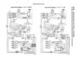
If one live wire is identified and goes to the harness, connect the said wire with an alligator clip to the meter's test lead and the other test lead attached to ground. Play, bend or twist the harness and see if the voltage will go away. if not instead of rewiring the entire harness, just ran a new kill wire from the engine terminal block to the ignition switch. This is just one wire instead of many wires. If you decide to do this, make sure you tape off the disconnected live wire to prevent shorts. Here's wiring diagram to help you. You might want to enlarge and print it to make it more readable.
 

Attachments

  • photo318684.jpg
    photo318684.jpg
    444.3 KB · Views: 0

puffitu

Chief Petty Officer
Joined
Dec 30, 2018
Messages
555
Thank you Jiggs
i already have printouts and yes there are some mismatched colored wires as you mentioned. I need to mention that the prev owner installed a funky switch at the engine cowl. Here’s how it works; you can start the engine regardless whether the switch is on or off, however, to shut it down it needs to be on. Lanyard switch is wired to ignition switch correctly but it does nothing when I pull the clip or not. The existing wire harness is original and some connections are loose so you think it’s ok for me to bypass it by using wire connectors or put in a terminal ?
 

Jiggz

Captain
Joined
Oct 23, 2009
Messages
3,909
So what is the function of the "funky switch" at the cowling? How many wires are running from it? How many positions, i.e. single throw (of-off), double throw (on-off-on), etc. Can you post a pic of the switch and also the connections at the back? Let me take a look at the funky switch first before continuing on.
 

puffitu

Chief Petty Officer
Joined
Dec 30, 2018
Messages
555
Thank you Jiggs
i already have printouts and yes there are some mismatched colored wires as you mentioned. I need to mention that the prev owner installed a funky switch at the engine cowl. Here’s how it works; you can start the engine regardless whether the switch is on or off, however, to shut it down it needs to be on. Lanyard switch is wired to ignition switch correctly but it does nothing when I pull the clip or not. The existing wire harness is original and some connections are loose so you think it’s ok for me to bypass it by using wire connectors or put in a terminal ?
 

Attachments

  • photo318691.jpg
    photo318691.jpg
    1.4 MB · Views: 0
  • photo318692.jpg
    photo318692.jpg
    1.4 MB · Views: 0
  • photo318693.jpg
    photo318693.jpg
    1.7 MB · Views: 0

Jiggz

Captain
Joined
Oct 23, 2009
Messages
3,909
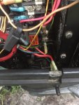
OK, so the funky switch has two wires. The red wire is obviously a hot wire. And the other wire colored green or maybe blue, where does it go? If you follow the color scheme, the green wire is supposed to be the choke wire. However, since this is a personal alteration, we can only guess. But if it is blue then it should go to the stop/lanyard switch. So where does the green or blue wire goes to?

It cannot be bypassing the lanyard, since the lanyard although normally close stays open as long as the clip is inserted. To bypass it shouldn't take a remote switch at the cowling, instead it can just be disconnected from the ignition switch M terminal. And if this is to bypass the lanyard switch why is it connected to a red hot wire? When it should just be blue (or maybe green) and white in parallel to the stop/lanyard switch.

Maybe it is a stop switch so when the owner gets done flushing the motor he can just turn it off locally from this switch instead of climbing back to the boat. And what he should have done is parallel two wires, white and blue (same as the lanyard switch, see diagram) to this switch instead of the red hot wire.

Have you tried disconnecting the red wire from the switch and do a voltage reading on the blk/yel wire and ground to see if there is Zero voltage? It looks like the switch is a simple single throw, on-off position. And it is normally in the off position (to allow the engine to run) and should shut down the motor (if running) when placed in on position.
 

puffitu

Chief Petty Officer
Joined
Dec 30, 2018
Messages
555
Maybe it is a stop switch so when the owner gets done flushing the motor he can just turn it off locally from this switch instead of climbing back to the boat. And what he should have done is parallel two wires, white and blue (same as the lanyard switch, see diagram) to this switch instead of the red hot wire.

Have you tried disconnecting the red wire from the switch and do a voltage reading on the blk/yel wire and ground to see if there is Zero voltage? It looks like the switch is a simple single throw, on-off position. And it is normally in the off position (to allow the engine to run) and should shut down the motor (if running) when placed in on position.

Thanks Jiggz
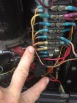
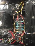
yes the two wires are large gage wires. Its a blue wire and not the green choke wire. The blue wire coming out of the funky switch runs back towards center console( I still have to trace as to where it connects to) and the red wire out of the funky switch connects to engine terminal as where you see my two fat fingers pointing to.
 

Jiggz

Captain
Joined
Oct 23, 2009
Messages
3,909
It's most likely a "local stop switch" but was wired wrong. To correct the problem, disconnect the red wire and tape if off for now (until you are sure of what is the funky switch is for). Disconnect also the blue wire and tape it off. To make this a "local stop switch) all you need is to connect a wire (preferably a blue wire) from the switch terminal to the blk/yel wire on the terminal block. Then connect a white wire from the other switch terminal and connect it to ground.

This is with the assumption the local switch is a normally open type switch. Meaning when in Off position, there is no continuity between the two terminals. And when in On position there is continuity. Test for continuity first before making the connections (after disconnecting both wires).

Or if you don't want a local stop switch, just disconnect the two wires, tape if off and then test for voltage between the blk/yel stop wire to ground. If zero voltage then you should be good to go.

The other thing to consider also, aside from being a local stop switch is that this could also be an on-off switch for the charging circuit. This is because the heavy gage red wire is actually connected to the red charging wire on the terminal block (trace the other red wires in the terminal block to see if one red wire goes to the rectifier. Again, you need to trace where the blue wire goes to.
 
Last edited:

puffitu

Chief Petty Officer
Joined
Dec 30, 2018
Messages
555
Traced the blue wire from funky switch and it connects to M terminal on back of the control box ignition switch on center console where another blue wire runs off to the lanyard.
id rather just get rid of the funky switch-
 

Jiggz

Captain
Joined
Oct 23, 2009
Messages
3,909
Well if that is the case, you already know what to do. Just disconnect and tape off the wires separately. And finally, check voltage between the stop blk/yel wire and ground and you should get zero. Or if you want to keep the local stop switch,I already explained earlier. Let me know if you want a simple wiring diagram for that. Enjoy!
 

puffitu

Chief Petty Officer
Joined
Dec 30, 2018
Messages
555
Jiggz you are awesome
and just for sake of argument please forward the simple diagram for a less funky switch...🤙
 

Jiggz

Captain
Joined
Oct 23, 2009
Messages
3,909
Will do. I still need a confirmation on the voltage test of the blk/yel wire after taping off the wires separately off the funky switch.
 

puffitu

Chief Petty Officer
Joined
Dec 30, 2018
Messages
555
As you said I’m getting zero between blk/yel stop and ground after taping off the funky connections. Additionally the big fat red wire was connected to ground on engine terminal and as I said before the blue wire off the funky connected to the blue M term on ign switch. Am I right to assume that all that switch does is a continuity switch to act as a lanyard? Pardon my lack of correct terminology. I haven’t tested the existing lanyard switch as it started to rain like crazy here but something tells me it’s not doing anything in either position just by the looks of it-trying to upload a pic of where the fat red wire was connected to but it’s saying the picture file is too large...I’ll try to reformat
 

puffitu

Chief Petty Officer
Joined
Dec 30, 2018
Messages
555
It finally let me upload the pic. So the red wire off funky switch connected to where my flat head screwdriver is pointing
 

Attachments

  • photo318748.jpg
    photo318748.jpg
    1.3 MB · Views: 0

Jiggz

Captain
Joined
Oct 23, 2009
Messages
3,909
If the two terminals below the fat red wire from the funky switch are connected to ground and the blue wire connects to the M terminal of the ignition switch, then this switch is absolutely a local stop switch, except the previous owner used a wrong color of wire which should have been black instead of red.

With wires taped off from the switch and zero voltage between ground and blk/yel wire, does the motor start and run? When running can you turn it off from the ignition switch? How about with the lanyard or safety switch?

Can you also post a pic of the lanyard switch?
 
Last edited:

puffitu

Chief Petty Officer
Joined
Dec 30, 2018
Messages
555
Hey Jiggz

I didn't get a chance to do any further tests due to the fact that its been raining here for 40 days and 40 nights seems like. but today I plan to do the tests you suggested with the funky disconnected. after giving it some more thought, ive decided to put the funky local stop switch at the helm rather than at cowling. pending tests ofcourse
 

Jiggz

Captain
Joined
Oct 23, 2009
Messages
3,909
Great. Let us know of you test results and also the voltage on the stop wire now that the switch is connected again. And if voltage is present again, do further testing to find out which of the two wires is hot, if any.
 

puffitu

Chief Petty Officer
Joined
Dec 30, 2018
Messages
555
Ran the motor with the funky wires taped off but not able to shut engine down via just turning the key off. As stated I put the funky at the helm; ). Inspected the lanyard switch and it tested good using continuity. Checking connections on the ignition switch against wiring diagrams.
 

Jiggz

Captain
Joined
Oct 23, 2009
Messages
3,909
Probably mis-wired at the ignition switch or the ignition switch is faulty and the previous owner instead of replacing it decided just to add a stop switch. And the switch is not that expensive and really easy to replace. It's only a matter of choosing either a short or a long barrel ones. See if this will help:

Click image for larger version  Name:	 Views:	1 Size:	30.0 KB ID:	10786757
 
Top