Inverter with shore power - Question ???

KD4UPL

Senior Chief Petty Officer
Joined
Feb 13, 2010
Messages
669
As I think you've discovered your inverter is much more than that, it's also a transfer switch and battery charger. If the system was installed and programed right the operation of the 120v system should be fairly seamless and automatic. The inverter will invert when no shore power, charge when there is, and automatically switch between the two modes.
The Xanbus is Xantrex's fancy name for the network that their components use to communicate. It's run with standard Ethernet cables but it's not an Ethernet system, it proprietary.
I would recommend that you get a Xantrex charge controller so it will also communicate with the other components you have. I assume you have the System Control Panel (SCP) already? If not you should get one so you can really see what your inverter is doing. The Xantrex charge controller you want is the XWMPPT60-150.
A 100 watt panel is not much. You can probably find a 325 watt panel for about the same price or even less if you look around. You'll never get the equivalent of 50 watts for 12 hours unless you live in some very special areas of the southwest and have the panel oriented perfectly on a very clear sunny day. In most areas of the country you can expect anywhere from 300 to 400 watt hours from a 100 watt panel on an average day if it's properly oriented and tilted. I expect you were going to mount yours flat which will reduce the output even further.
 

alldodge

Moderator
Staff member
Joined
Mar 8, 2009
Messages
42,054
Only 30 Amp shore power charger for that many Bats
My 95 Formula came with a 3 bank 50 Amp with 3 Bats (Start, House, Gen). I changed it out to a Charles 40 Amp because of no AGM selection. This winter changed again to 50 Amp ProNautic 1250P

Mostly a mute point for your setup Ted because you don't use shore power while on the hook
 

Bob Sander

Petty Officer 2nd Class
Joined
Nov 29, 2021
Messages
120
View attachment 354777

Here is my handy work with a schematic - keep in mind that this is for maintaining the batteries only (think trickle charge) as the boat sits at the mooring.

It would need to maintain the 2 Mercathode systems and the radio keep-alive, and maybe 1 or 2 other things - God only knows what.

Assuming not at full power throughout the day, If I get an average of 50 watts for 12 hours per day = 600 watt hours (0.6 kwh)

Assuming 13.5 volts to charge the batteries = 44 amp-hours each day.
Cool project and that would certainly work.... but sorry man.... gotta ask... Are you expecting some form of major savings out of this or is it January and you're just bored :)

That certainly won't supply enough power by itself when you are in the water... unless of course you shut the boat down dead. You will still need a shore connection, at least if you plan on keeping the beer fridge going along with the bilge pump and other stuff.

And out of the water by your garage... well... in my part of the world a battery charger plugged into my garage outlet would be a maintenance free cost of about $1.80 a month.
 

tpenfield

Moderator
Staff member
Joined
Jul 18, 2011
Messages
18,039
Cool project and that would certainly work.... but sorry man.... gotta ask... Are you expecting some form of major savings out of this or is it January and you're just bored :)

That certainly won't supply enough power by itself when you are in the water... unless of course you shut the boat down dead. You will still need a shore connection, at least if you plan on keeping the beer fridge going along with the bilge pump and other stuff.

And out of the water by your garage... well... in my part of the world a battery charger plugged into my garage outlet would be a maintenance free cost of about $1.80 a month.
No . . . the boat will be on a mooring (not a slip) during the summer. So, no access to shore power. I'm not running anything while the boat is not in use. Just to keep the batteries charged for the little current draw that exists with the Mercathode, radio memory, etc.

I'm not sure you are understanding that.
 

tpenfield

Moderator
Staff member
Joined
Jul 18, 2011
Messages
18,039
Quick update. . .

I ordered a 100 Watt marine 'kit' from Renogy. Includes flex panel, controller, wiring. Since the controller is a single output, I'll be adding the diodes in the wiring to isolate the 3 battery banks from sharing electrons. :LOL:
 

alldodge

Moderator
Staff member
Joined
Mar 8, 2009
Messages
42,054
Simple a cheap to build a 3-bank isolator for sure. Cheapest ready made is about $50. Only good thing about ready made is that its ready made
 

tpenfield

Moderator
Staff member
Joined
Jul 18, 2011
Messages
18,039
The 100 Watt solar kit arrived yesterday. It's a good thing I went with only 100 watt . . . the solar panel is quite large. Anything bigger might have taken up too much space up top on the arch.
 

bruceb58

Supreme Mariner
Joined
Mar 5, 2006
Messages
30,537
I doubt you are going to get much charge going to the batteries through isolation diodes with that Renogy controller. There will be enough voltage drop across the diodes to severely limit you. You will find out soon enough though. There are controllers out there that you can increase the voltage output to compensate for them if this doesn't work.

I know you are using this just to keep batteries topped off.
 

tpenfield

Moderator
Staff member
Joined
Jul 18, 2011
Messages
18,039
The diode will drop the voltage about 0.7 volts I'm hoping the controller can put out enough voltage to overcome and still have enough to charge the batteries. According to the spec's if looks like it should be OK. I've got a battery or 2 to test it with before installation.
 

bruceb58

Supreme Mariner
Joined
Mar 5, 2006
Messages
30,537
The diode will drop the voltage about 0.7 volts I'm hoping the controller can put out enough voltage to overcome and still have enough to charge the batteries. According to the spec's if looks like it should be OK. I've got a battery or 2 to test it with before installation.
If the solar controller that comes with the kit is the Renogy Wanderer, then the boost voltage is at 14.6V(flooded) which means the voltage at the battery will be 13.9V which means you will get a little bit of charge. Problem is, it will go into float voltage sooner than it normally would and it will float the batteries at something less than a fully charged battery voltage of 12.5V or so. If that is adequate for you, it will work...it just won't keep your batteries at 100%.

I use a lot Victron stuff myself on my travel trailer and you can actually set the voltages to whatever you want including the absorption and float voltages to a higher level to make up for the diode drop. There are also some other controllers that have remote voltage sense which whatt you really want. Only problem with what you are doing is is that it will only sense one battery.

Another option, in case you already use ACRs between your batteries, is to just connect the solar controller to one battery and let the ACRs turn on while the solar controller is charging the batteries. That may or may not work depending on the trigger points of the ACRS. Worked fine for my boat. I had a BlueSea ACR between my 2 batteries. I had a cheap Epever solar controller and a 50W flexible Rich solar panel. Worked great.
 
Last edited:

tpenfield

Moderator
Staff member
Joined
Jul 18, 2011
Messages
18,039
I'll do some testing and see how well it works . . . or not.
 

tpenfield

Moderator
Staff member
Joined
Jul 18, 2011
Messages
18,039
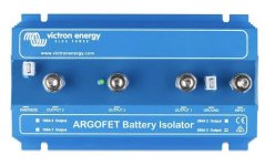
@bruceb58 - Thanks for raising this issue as it has prompted me to do some more research. Maybe something this will do the trick in terms of avoiding voltage loss.

"Victron ArgoFET Battery Isolators"​

ARGOFET-1.jpg

The product information states that it is an FET (Field Effect Transistor - from my electronics days) isolator and differs from diode isolators in that the voltage loss is only about 0.02 volts.
 

bruceb58

Supreme Mariner
Joined
Mar 5, 2006
Messages
30,537
Yep...that would do it.

Do you use ACRs?

Twin engines?
 
Last edited:

sam am I

Commander
Joined
Jun 26, 2013
Messages
2,169
Couple things.....

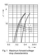
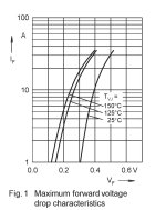
You can reduce the Vf(forward break over voltage) of the typical 0.5V-0.7V of a standard diodes to a Vf of 0.2-0.3V by selecting/using "Schottky" diode's. This might be more acceptable with a 14.6V supply in the example above of the "Renogy Wanderer, then the boost voltage is at 14.6V"

@ 25C/1A, Vs - Vf = 14.6 - 0.3V = 14.3V(DSS20-0015B Vf verse If below)

L234-1547539a.jpg


On a longer note and in regards to the Argo FET ISO,

If you use the "Argo FET ISO", it'll work okay, but just understand its limitations and framework to work within.

Unlike diodes, the Argo FET ISO is analogous and will work just like 3 mechanical contractors (SPST Switches/Relays) all wired in parallel, but solid state of course.

It is NOT a smart device either/doesn't work like an ACR.

When *turned on, all your battery's(3?) will be paralleled/connected together and will equalize at that instant(**current can/will flow in either direction through each switch when the Argo FET ISO is turned on/energized),

It has no brains what so ever and whatever condition the batt's are initially, it'll just put and keep the 3 battery's tied together while on and "charging them all simultaneously" with whatever charge source you have and then of course Isolating(opening all the switches, no current either way, any switch) when turned off.

Which is fine as it will keep the batts all topped off while the suns out and will isolate each from each other when the "energize signal" is turned off.

**The reverse(current)is also true too!! And again, unlike diodes and their PN junction anogous to a one way valve, if the Argo Fet gets/is LEFT ON, and for example the sun goes down and charge current goes below any load current, and for example, batt/load 1 has some current draw, batt 2 and batt 3 will also share that draw (recall the batts are paralleled still while Argo is on, discharge current is NOT blocked like a PN junction of a diode)..........

Just make sure the Argo gets shut off esp if there's ANY leakage current on any one bank and the sun goes down/nuclear winter.

*I assume to energize it you'll use one of the batt's voltage? This will then be a constant on then right? Not good!! Or your plan is and does your controller have a DC output of sorts that is 12V with sun and 0V off w/o sun? Maybe better,...

**See "anti series" (decent write up/basic understanding) config of FET's body diodes limitations and bilateral current flow when on)......


Think I'd use Schottky diodes and live with 0.2V/0.3V Vf, much simple and the batts will be more or less fully charged, no worried about reverse current, diodes provide 100% isolation 100% of the time and NO ISO control signal/management to worry about.
 

Attachments

  • L234-1547539.jpg
    L234-1547539.jpg
    105.2 KB · Views: 2
Last edited:

tpenfield

Moderator
Staff member
Joined
Jul 18, 2011
Messages
18,039
Thanks for the technical info guys. My plan is to connect all of this 'stuff' up before installation and see how it does in charging the battery of my Boston Whaler skiff.

The boat itself (Cruisers Yacht 338) charges the house battery bank (3 batteries) from the port engine and each engine also charges is own battery bank (2 batteries each). When on shore power (seldom), the batteries charge from the shore power unit.
 
Top