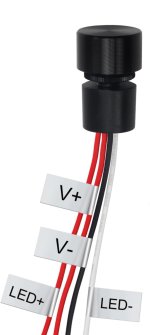
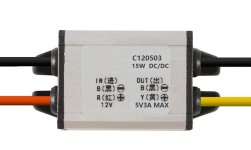
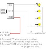
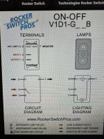
Just got a new Sylvan Mirage Cruise pontoon and I couldn’t justify paying an arm and a leg for fancy extra lighting. I have done a ton of projects with LED and COB strips before so that part didn’t worry me. The console comes with a full set of rockers and matching connectors on the harness even if you didn’t upgrade to have the accessories installed. For example, pump switch at the panel controls nothing but there is a female Delphi connector under the boat just waiting to be hooked up. Wash down station here I come  Definitely was pleasantly surprised that every spot where I ran my interior lighting wires had a corresponding connector under the boat just waiting to be hooked up. Bought a bunch of male Delphi connectors and saved myself tons of time having to run everything back to the console myself. Since this is my first new pontoon (my last one I redid the entire electrical myself which was somehow less confusing) I am unsure about how to splice in certain components. One switch needs a step down converter between the switch and the existing four connectors coming off the harness. Another switch needs a dimmer before it splits off to the five connectors. Both the step down converter and the dimmer have a positive and negative in and out. I verified they work when connected between one existing connector and the light itself, however I want them to control ALL of the branches of the lighting circuit. Which would mean slotting it in right where the wiring starts from the rocker switch at the panel.
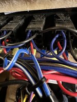
My plan was to pull the current accessory wire from the switch and replace it with the positive of the component. Issue is what to do with the negative in and out? There is no bus bar for the grounds and the switches themselves have Daisy chained grounds but they don’t extend from the panel. It appears that every ground is running back to the battery in a huge mass of black wires.
Thought about adding a ground bus bar in the console but I am still questioning how I add these components in. For example, if I replace the existing wire from the back of the switch for the courtesy lights with the positive in on the dimmer switch and connect the same courtesy light wire to the positive out of the dimmer… where do I connect the negative in and out?
Attaching the best photo I could get of the existing panel wiring. Appreciate any advice! Really don’t want to mess up the brand new wiring if I can help it…


