Ignition wiring question 72 350

salvageyard saviour

Petty Officer 2nd Class
Joined
Oct 28, 2018
Messages
162
I'm pretty stupid when it comes to electrics.

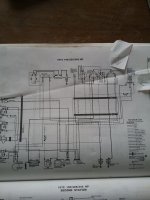
If I go by schematic (Clymer). What makes the engine stop when the key is turned off?

The key power isn't connected to the power distribution going to the coil.
Should I trust Clymer? Mercruiser manual and pre 72 OMC has a wire from the key to the power distribution or ballast.

Alternator is early prestolite and regulator is 3 wire relay.
There was no ballast resistor (I'll put it back) and PO had put in a spaghetti wire of a mess bypassing the OMC harness (still there), also this boat originally had a 307 or 327 not the 74 350 in it now. Everything else is year appropriate for 72 245 hp.

I'd like to get it back to the way was originally.

Again, I don't get what stops the alternator from continuing to power the coil when key is turned off

Attached is a photo of the Clymer diagram
20220102_103651.jpg
 

kenny nunez

Captain
Joined
Jun 20, 2017
Messages
3,075
I can feel your pain. 72 was the last year OMC used the hard plastic harness connectors that were prone to cause bad connections. Even if your ’s is the round rubber style just the age of the wire‘s insulation has to be the root cause, it is probably crumbling if you just touch it.
The regulator wire needs to be traced back to a live + battery feed. For the time being cut the wire feeding the regulator and run a new wire from the ignition “I” terminal to the regulator.
The original resistor may have been replaced with a resistor wire.
I have in the past re wired engines using a barrier strip with ring terminals.
Hopefully the wire harness from the instrument panel to the engine are still in good condition.
Genuine OMC service manuals are still available and Crowley Marine has OMC original parts and possibly a wire harness for your model.
 

salvageyard saviour

Petty Officer 2nd Class
Joined
Oct 28, 2018
Messages
162
Yes it's a rats nest of wires. I want to clean it up and use the original harnesses. Everything about the yellow connector looks okay, but the rest is a mess.
The connector at the helm was cut off and wires twisted together and then wires were run to engine bypassing harness. Ohm meter says wiring is solid, don't know why po did what they did.

Question, when you say cut the regulator wire. Do you mean the purple going to the helm or the light green going to the alternator field ? (I did say I'm electrically challenged).
How would this make the engine stop when key is turned off? Should I also run the purple wire from coil resistor to ign "I" ?

Or, does no 12v feed to regulator (turn key off) mean no charge output ,thus no spark
 

salvageyard saviour

Petty Officer 2nd Class
Joined
Oct 28, 2018
Messages
162
By the way, it's on a diy stand that I've had it running with temporary wiring and bare essentials. Junk alternator just for the water pump belt.
The hull needs A LOT of glass work next summer. In the meantime I'll have the instrument panel out and would like to get it all wired to run on the stand as if it were in the boat using all the harnesses and engine accessories. I'll only bypass the neutral switch for this as there will be no drive or throttle controls yet.
 

kenny nunez

Captain
Joined
Jun 20, 2017
Messages
3,075
Take a close look at the starter solenoid, the wire on the 3 o’clock terminal is the by pass that feeds the coil with 12 volts when cranking, it could be possible that the battery cable is contacting the small terminal back feeding the ignition.
Look closely at the wiring diagram on the far lower left of the page.
 

kenny nunez

Captain
Joined
Jun 20, 2017
Messages
3,075
Contact Crowley Marine @ 303 355 3355.
0383339 should be the engine harness, they are showing 1 in stock.
 

salvageyard saviour

Petty Officer 2nd Class
Joined
Oct 28, 2018
Messages
162
Thanks Kenny for your patience.
Guess I should have clarified. I think I ran you on the wrong side of the bouy.
I don't have this problem now with my temporary wiring. I have the ballast wired directly to the battery and full 12v from the starter solenoid . To stop I just pull the ballast wire. Junk alternator just for the water pump belt so no charging wires.

Where I'm confused Is if I put good alternator, regulator and permanent wiring per diagram, how would the engine stop if the ignition switch doesn't appear to be part of that run circuitry? Arrows pointing at top right of diagram.

Should I ignore Clymer and wire the purple wire from the regulator and also the purple wire from coil resistor to the "I" of ignition switch? Or a wire from "I" to that purple wire cluster at the temperature gauge?

Is the wire from the regulator both the sense and excite ?
 

kenny nunez

Captain
Joined
Jun 20, 2017
Messages
3,075
The wire from the regulator supplies regulated current to the field circuit to excite the alternator as you said. It could be possible that the regulator is internally shorted feeding current to the ignition circuit. Try disconnecting that wire.
The Clymer diagram shows a volt meter. At that time all OMC instrument panels had amp meters to indicate charging.
If you want my cell is 504 427 6905. I am on central time.
 

salvageyard saviour

Petty Officer 2nd Class
Joined
Oct 28, 2018
Messages
162
Thanks Kenny,
I'll stop looking at the Clymer and get a real service manual. I'm sure the new harness will help being sure I'm not chasing other problems.

May even do away with this alternator, regulator set up for a 1 or 3 wire alternator for simplifying things.

I'll let you know how it goes when I start the wiring.
 
Top