ignition switch source for fuel pump relay kit?

Nextelbuddy

Petty Officer 2nd Class
Joined
May 4, 2020
Messages
156
Performing a mechanical to electric fuel pump on my mercruiser 5.7 1996 Sea Ray 210.

Using a Carter Marine 5 to 7 PSI fuel pump, a relay kit I got from summit racing that has a oil pressure safety switch, fuse kit, relay and wiring etc.. comes with all the wiring and connectors and some instructions of the wiring diagram everything seems pretty simple.

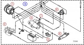
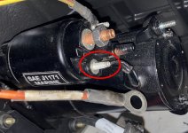
Looks like there is an extra pole on the starter I can take advantage of for the starter signal to the "S' pole of the oil pressure safety switch.

The part I get hung up on is the ignition switch source that goes to the "I" pole of the oil pressure safety switch.

Is the expectation that I run the wire for ignition all the way to the front of the boat to the actual ignition switch?

I've been researching all night and I see tons and tons of threads to talk about installing a fuel pump relay kid with an oil pressure safety switch wired to the starter etc etc. Tons of wiring diagrams of how people do it but nothing about the ignition switch.

So maybe I'm thinking about it too hard but I wasn't sure if I'm actually supposed to just run the wire directly to the front of the boat get under the dash pull out the ignition switch and find the wire to tap into there? Or is there another source on the engine that gets ignition source signal that I can take advantage of?
 

MichaelBC

Petty Officer 2nd Class
Joined
Feb 28, 2020
Messages
110
This pretty simple if you tak a look at the wiring diagram. You do not need to pull a cable to the front. You can use the purple cable on the alternator or you could also use the + connector of the ignition coil. This goes to the oil pressure switch then.

So the pump only gets power when oil pressure is above a certain level. To support the pump when the engine should start and the oil pressure is low there is another connection to the starter magent switch. So a soon as the starter cranks the engine the pump starts filling the carburetor.
 

Attachments

  • 1.jpg
    1.jpg
    112.6 KB · Views: 14
  • 2.jpg
    2.jpg
    132.2 KB · Views: 15

Scott Danforth

Grumpy Vintage Moderator still playing with boats
Staff member
Joined
Jul 23, 2011
Messages
47,562
why would you replace a $49 mechanical fuel pump that will last 30 years with a $89 electric pump with $15 worth of relay, oil pressure switch and wiring that will only last about 10?

mechanical fuel pumps are superior to electric pumps in so many ways.
 

alldodge

Moderator
Staff member
Joined
Mar 8, 2009
Messages
40,760
Agree sort of with mechanical will last, but no so sure about the amount of time. Many like to change to electric so the fuel bowl fills up faster if its dry. They still use mechanical pumps on high performance motors built today

The easy fix without a relay
Fuel pump 3 pin switch.jpg
 

Nextelbuddy

Petty Officer 2nd Class
Joined
May 4, 2020
Messages
156
why would you replace a $49 mechanical fuel pump that will last 30 years with a $89 electric pump with $15 worth of relay, oil pressure switch and wiring that will only last about 10?

mechanical fuel pumps are superior to electric pumps in so many ways.
i know i know i see it emphasized all the time, unfortunately when i did vortec heads, i ended up with a comp cam camshaft upgrade that does not support mech fuel pump (missing the fuel pump lobe) so we used a blck off plate for the old mech fuel pump location on the non vortec block.


the kit i have is the TANKS fuel pump safety switch kit.

PXL_20210713_004802899.jpg


I still not understanding the example offered that showed just using safety switch only but ill look again and see if it makes sense.


if i wanted to use my kit with the relay and safety switch then it looks like i can just grab ignition signal from the purple cable on the alternator or the + connector of the ignition coil and run that to the "I" pole o the Oil pressure switch and then the "S" pole of the oil pressure switch to the extra unused pole on the starter?
 

alldodge

Moderator
Staff member
Joined
Mar 8, 2009
Messages
40,760
I still not understanding the example offered that showed just using safety switch only but ill look again and see if it makes sense.
In my example, you can use the same switch you have now. There is a common (C), normally open (NO) and normally closed (NC) terminals. The Yellow/red which is currently connected to your start is connected to the NC terminal. Connect the NO side and connect to the purple wire on the motor. The purple will come from the excite on the ALT or the coil. Connect the C to the pump.

Motor cranks and power feeds on the NC side to the pump. Once it starts and oil pressure comes up the C is connected to the NO side

In your drawing it happens the same way just uses a relay. The P terminal is the C in mine. The I is the NO and the S is the NC. Yours draws less current thru the motor ignition then mine
 

flashback

Captain
Joined
Jun 28, 2002
Messages
3,708
I just did that mod on my 5.7 and used a lead off the ignition coil because it was close to where I mounted the relay..
 

Nextelbuddy

Petty Officer 2nd Class
Joined
May 4, 2020
Messages
156
I just did that mod on my 5.7 and used a lead off the ignition coil because it was close to where I mounted the relay..
So I found your original pictureIMG_20210624_145900417.jpg

It looks like on the relay you have the relay mounted right on top of the master circuit breaker

The main red power wire for the relay you have going to the main circuit breaker instead of the battery

Then the purple and white wire coming off the relay you have going to the fuel pump area

Then the yellow wire on the relay looks like your trigger wire or ignition wire That is going to the "P" pole of the oil pressure safety switch

Then you have the "I" ignition pole of the oil pressure safety switch going to the 2 pole circuit connector it's right in the front of the main circuit breaker relay area...

Then you have a purple wire "P" pole coming off the oil pressure safety switch going to the coil?

Do I have that remotely correct?
 

nola mike

Vice Admiral
Joined
Apr 22, 2009
Messages
5,078
So I found your original pictureView attachment 345290

It looks like on the relay you have the relay mounted right on top of the master circuit breaker

The main red power wire for the relay you have going to the main circuit breaker instead of the battery
Yes, don't run it directly to the battery, messy and isn't fuse protected

Then the purple and white wire coming off the relay you have going to the fuel pump area
Dunno what these are in his setup
Then the yellow wire on the relay looks like your trigger wire or ignition wire That is going to the "P" pole of the oil pressure safety switch
Yes. Not ignition, should be the relay trigger from the switch, 12v when switch is closed
Then you have the "I" ignition pole of the oil pressure safety switch going to the 2 pole circuit connector it's right in the front of the main circuit breaker relay area...

This should go to a switched 12v source, coil pos for example, or choke
Then you have a purple wire "P" pole coming off the oil pressure safety switch going to the coil?
That's the yellow wire, remember?

Do I have that remotely correct?
I think you might be getting confused by the colors in the instructions you posted. I on the switch goes to switched power. P is the 12v source to the relay. S goes to the starter or slave solenoid and gets 12v only when cranking. At the relay on your diagram, when you get 12v from the op switch the red and orange wire are connected and you get 12v from the red wire to the pump.
 

flashback

Captain
Joined
Jun 28, 2002
Messages
3,708
Yep that's how I did it. There is a fuse link right behind the relay that you cant see for power. Wanted to keep my wiring short as i could and convenient access in case.
 

flashback

Captain
Joined
Jun 28, 2002
Messages
3,708
Yep that's how I did it. There is a fuse link right behind the relay that you cant see for power. Wanted to keep my wiring short as i could and convenient access in case.
And nola mike, your spot on, once my head understood what needed to happen the 3 pole oil switch gave options. The relay may overheat so that is on the watch list.
 

nola mike

Vice Admiral
Joined
Apr 22, 2009
Messages
5,078
And nola mike, your spot on, once my head understood what needed to happen the 3 pole oil switch gave options. The relay may overheat so that is on the watch list.
Relay shouldn't overheat, its function in life is to take the strain off the rest of your wiring 😁
 

Nextelbuddy

Petty Officer 2nd Class
Joined
May 4, 2020
Messages
156
Relay shouldn't overheat, its function in life is to take the strain off the rest of your wiring 😁
That's why I was worried using a 12volt switch source from the coil because I didn't want to send unneeded current/amps through the oil pump safety switch.
Not sure where the slave solenoid is
 

nola mike

Vice Admiral
Joined
Apr 22, 2009
Messages
5,078
That's why I was worried using a 12volt switch source from the coil because I didn't want to send unneeded current/amps through the oil pump safety switch.
Not sure where the slave solenoid is
You aren't. That 12v only is used to trigger the relay, which draws very little current. With the relay all of the current goes from your fat short red wire through the relay, on to your fat short wire from the relay through to the pump. None of it (pretty much) goes through the switch.
 

Nextelbuddy

Petty Officer 2nd Class
Joined
May 4, 2020
Messages
156
Yes, don't run it directly to the battery, messy and isn't fuse protected


Dunno what these are in his setup

Yes. Not ignition, should be the relay trigger from the switch, 12v when switch is closed


This should go to a switched 12v source, coil pos for example, or choke

That's the yellow wire, remember?


I think you might be getting confused by the colors in the instructions you posted. I on the switch goes to switched power. P is the 12v source to the relay. S goes to the starter or slave solenoid and gets 12v only when cranking. At the relay on your diagram, when you get 12v from the op switch the red and orange wire are connected and you get 12v from the red wire to the pump.
So what exactly is the slave solenoid? My circuit breaker setup looks a little different than than his. Here is mine, is this the slave solenoid circled in red?

PXL_20210713_005828486~3.jpg


So think I have the wiring down now.

Oil pressure safety switch:
"P" - to trigger wire on relay.
"S" - to empty pole on starter or slave solenoid
"I" - to + Positive pole on external coil "12v switched source"

Relay:
Pin 30 - battery with fuse/circuit breaker or to engine circuit breaker assembly in too of engine
Pin 87 - fuel pump +12v
Pin 86 - trigger wire to "P" pole of oil pressure safety switch
Pin 85 - engine or battery ground

Fuel pump:
+12v - Pin 87 of relay
- pole - engine or battery ground

How does that sound?
 

nola mike

Vice Admiral
Joined
Apr 22, 2009
Messages
5,078
So what exactly is the slave solenoid? My circuit breaker setup looks a little different than than his. Here is mine, is this the slave solenoid circled in red?

View attachment 345336
Looks like it, I can't tell for certain without seeing the whole thing. Should have 4 terminals,2 yellow black wires. It's just a relay that drives the starter.
So think I have the wiring down now.

Oil pressure safety switch:
"P" - to trigger wire on relay.
"S" - to empty pole on starter or slave solenoid
"I" - to + Positive pole on external coil "12v switched source"

Relay:
Pin 30 - battery with fuse/circuit breaker or to engine circuit breaker assembly in too of engine
Pin 87 - fuel pump +12v
Pin 86 - trigger wire to "P" pole of oil pressure safety switch
Pin 85 - engine or battery ground

Fuel pump:
+12v - Pin 87 of relay
- pole - engine or battery ground

How does that sound?
Sounds good.
 

achris

More fish than mountain goat
Joined
May 19, 2004
Messages
27,468
That's why I was worried using a 12volt switch source from the coil because I didn't want to send unneeded current/amps through the oil pump safety switch.
The way Merc wire them originally is for all the pump current to run through oil pressure switch, not a relay coil amount, the WHOLE pump. :eek:

By setting up the relay (which is a good thing) you're actually reducing the current running through the wiring to the coil, and through the pressure switch...
 

Nextelbuddy

Petty Officer 2nd Class
Joined
May 4, 2020
Messages
156
So i followed my earlier suggested pinout diagram of:

Oil pressure safety switch:
"P" - to trigger wire on relay.
"S" - to empty pole on starter or slave solenoid
"I" - to + Positive pole on external coil "12v switched source"

Relay:
Pin 30 - battery with fuse/circuit breaker or to engine circuit breaker assembly in too of engine
Pin 87 - fuel pump +12v
Pin 86 - trigger wire to "P" pole of oil pressure safety switch
Pin 85 - engine or battery ground

Fuel pump:
+12v - Pin 87 of relay
- pole - engine or battery ground


i chose to mount the relay bracket right there on top of the circuit breaker box with the grounds underneath it. it made getting everything wires pretty simple and short.

Im not a fan of how busy the area looks with wires so i will try to clean it up a little more creatively. may wrap it all in wire loom so its not so colorful.

my orange wire coming from the relay is for the fuel pump and that will get wired in when the engine is installed so for now that's just bundled up out of the way.

i really like how easy it was to get to the starter solenoid, the main relay power from the main 50 amp circuit breaker (i hope that i tapped into the correct wire on the circuit breaker. not sire if i tapped into the pre or post circuit wire but i chose the smaller power wire over the larger wire which i thought was the feed wire from the battery)

PXL_20210715_013445321.NIGHT.jpg
PXL_20210715_013529747.NIGHT.jpg
PXL_20210715_014854467.NIGHT.jpg
 
Top