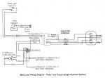
Could someone PLEASE point me to the trim wiring diagram for a 1977 Searay V200 with a Mercruiser 898 (2BBL 305 GM 5.0L)? I bought the Mercruiser Stern Drive Manual(s) volume 1 and II. P/N's C-90-68648 and C-90-71707 respectively because I was led to believe they would be what I needed. They weren't.
My trim limit switch and trim position sender's wires deteriorated and caused a failure at the 3 (black) button control and at the gauge. I replaced the wires between the harness and the trim pump and the ground but I was guessing because the wires had deteriorated so far they actually broken into pieces. The trim gauge pegs at the top end when the key's on but I cannot bring it down by rotating the sender itself (as indicated in the directions which accompanied the new trim switch kit). I believe I have it wired wrong. NOTE I am using jumper wires to mimic the actual wires because I want to make sure everything works before I remove the outdrive to get at the thru hull for the trim sender wires. ( OMG what an asinine design!!!!)
I'm not opposed to buying yet another manual ( I also purchased a CLYMER manual I hope is appropriate...but it hasn't arrived yet) but I'm hoping to get this wired properly this weekend ....but anything I order in hard copy won't get here for several days minimum.
plz help!


