high voltage to just one battery but not the other (from alternator)

jjisjj

Cadet
Joined
Jul 25, 2022
Messages
7
Hi,

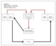
I have 2 batteries connecting to Honda BF225D outboard through a perko switch. When I use battery 1 to start the engine, everything was fine. When I switched to battery 2 to start the engine, the Honda ACG alert would beep continuously, indicating charging system is faulty. Use multimeter to measure and I got 16.9 volt which is consistent with the ACG alert -- alternator's output voltage is too high. The fact that battery 1 worked fine, I think alternator should be ok. The problem is probably battery 2 or the wiring related to battery 2.

The wire connection is a pretty typical and symmetrical with the exception that the black return wire from engine goes to battery 1 negative only (not terminal 2) , if I follow the wire:
when I use battery 1:
- battery 1 positive -> perko switch input 1 -> perko switch out -> engine/alternator -> battery 1 negative -> ground bus (connected to boat body) -> battery 2 negative
when I use battery 2:
- battery 2 positive -> perko switch input 2 -> perko switch out -> engine/alternator -> battery 1 negative -> ground bus (connected to boat body) -> battery 2 negative

To see battery 2 is good or not, I connected battery 2 this way and everything worked fine. This means battery 2 is not the problem.
- battery 2 positive -> perko switch input 2 -> perko switch out -> engine/alternator -> battery 2 negative -> ground bus (connected to boat body)

So the only culprit is a bad grounding somewhere along this path:
- battery 1 negative -> ground bus -> battery 2 negative

Is my assumption correct? Or are there other possibilities?

I cleaned all contact points with CRC contact cleaner carefully and tightened everything super tight, still the problem is there (battery 1 works fine, but when I use battery 2, I still got high voltage from alternator and ACG alarm). Worked on this all weekend and am stuck. I am absolutely clueless on what I can try next. Any suggestions?

Thanks a lot for your help!
 

Attachments

  • S1.JPeG
    S1.JPeG
    115.4 KB · Views: 5

Bt Doctur

Supreme Mariner
Joined
Aug 29, 2004
Messages
19,294
All battery neg`s should be connected together,Pos should be #1 and #2 on the battery switch. The charging system is showing a fault because its the engine is not connected to the battery neg.
 

jjisjj

Cadet
Joined
Jul 25, 2022
Messages
7
All battery neg`s should be connected together,Pos should be #1 and #2 on the battery switch. The charging system is showing a fault because its the engine is not connected to the battery neg.
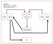
Thanks for the reply. The battery neg's are connected together in the diagram, although it's connected through a common ground. Are you suggesting that the wiring should be done this way instead (see attached, scenario 3)?
 

Attachments

  • S3.JPG
    S3.JPG
    110.9 KB · Views: 6

Bt Doctur

Supreme Mariner
Joined
Aug 29, 2004
Messages
19,294
not thru a common ground point, a strap from neg to neg and thats where you connect the neg from the motor to the neg of the battery terminal
 

dingbat

Supreme Mariner
Joined
Nov 20, 2001
Messages
16,083
The battery neg's are connected together in the diagram, although it's connected through a common ground.
Your getting an over voltage because your trying to push through too much current through too small of a ground wire.

Ideally, you run a negative battery cable between the two ground posts then tie the engine ground to one of the batteries.

Run a seperate line for accessory ground.
 
Last edited:

jjisjj

Cadet
Joined
Jul 25, 2022
Messages
7
Thank you both for the great suggestions. I think I tried that already but still got the same problem.

Let me try that again and remove accessory grounds to make sure. Thanks.
 

dingbat

Supreme Mariner
Joined
Nov 20, 2001
Messages
16,083
Thank you both for the great suggestions. I think I tried that already but still got the same problem.

Let me try that again and remove accessory grounds to make sure. Thanks.
OK, read through your post.

The 16.9V reading is suspicious unless the voltage regulator is damaged which your test seemed to confirm is not the case.

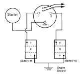
Your switch and batteries should be wired as below.
Main engine ground cable (-) goes directly to battery terminal.

Main engine positive (+) "starter" get connected to the COM terminal on the back of the switch.

Tie both batteries together at ground posts using a battery cable of equal or larger size (diameter) as the positive (+) cables.

I still say your grounds are the problem.
You don't have a problem with Battery 1 because the main engine ground is connected directly to the battery.

Battery 2 is a problem because you've increased the resistance in the ground path between the charge and battery 2.

When current drops voltage goes up.
Alternator output - 420w = 30A@14V. That same 420W output with a more restrictive ground path could result in charge of 24.9A@16.9V

What size ground wire between the two batteries?
How are they tied together?

1658853943107.png
 

jjisjj

Cadet
Joined
Jul 25, 2022
Messages
7
OK, read through your post.

The 16.9V reading is suspicious unless the voltage regulator is damaged which your test seemed to confirm is not the case.

Your switch and batteries should be wired as below.
Main engine ground cable (-) goes directly to battery terminal.

Main engine positive (+) "starter" get connected to the COM terminal on the back of the switch.

Tie both batteries together at ground posts using a battery cable of equal or larger size (diameter) as the positive (+) cables.

I still say your grounds are the problem.
You don't have a problem with Battery 1 because the main engine ground is connected directly to the battery.

Battery 2 is a problem because you've increased the resistance in the ground path between the charge and battery 2.

When current drops voltage goes up.
Alternator output - 420w = 30A@14V. That same 420W output with a more restrictive ground path could result in charge of 24.9A@16.9V

What size ground wire between the two batteries?
How are they tied together?

View attachment 366513
Thanks Dingbat!

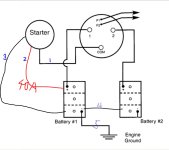
What you said totally makes sense. I connected the 2 batteries exactly the same way as the diagram you shared. To complete the picture, I also added additional wires to the diagram below. There are 3 wires going in/out of the engine (starter/alternator), I labeled them in the diagram in blue ink.
wire 1: red thick wire, I think this carries the heavy load
wire 2: red thin (relatively) wire, connect directly, with an inline 40A fuse, from battery 1 positive to the engine (not through switch).
wire 3: black thick wire, connect to battery 1 negative terminal

in additional to that, I have:
wire 4: connect battery 1 neg to battery 2 neg (4 AWG wire)
wire 5: connect battery 1 neg to the ground. (also 4 AWG wire)

With this setup, I still encounter the same problem.

I am going to buy a new set of 4 AWG wire (wire 4 and 5) and see if it works. Could be a bad wire?
 

Attachments

  • Capture.JPG
    Capture.JPG
    70.3 KB · Views: 4

dingbat

Supreme Mariner
Joined
Nov 20, 2001
Messages
16,083
Thanks Dingbat!

What you said totally makes sense. I connected the 2 batteries exactly the same way as the diagram you shared. To complete the picture, I also added additional wires to the diagram below. There are 3 wires going in/out of the engine (starter/alternator), I labeled them in the diagram in blue ink.
wire 1: red thick wire, I think this carries the heavy load
wire 2: red thin (relatively) wire, connect directly, with an inline 40A fuse, from battery 1 positive to the engine (not through switch).
wire 3: black thick wire, connect to battery 1 negative terminal

in additional to that, I have:
wire 4: connect battery 1 neg to battery 2 neg (4 AWG wire)
wire 5: connect battery 1 neg to the ground. (also 4 AWG wire)

With this setup, I still encounter the same problem.
Your wiring is still messed up

The “thin red” (#2) and thick red (#1) wires both go to the COM terminal on the switch.

The “engine ground” is the heavy black cable coming from the motor. This gets tied directly to a battery negative post.

You then run a heavy ground cable between the two negative battery posts to tie grounds together.
 
Last edited:

dingbat

Supreme Mariner
Joined
Nov 20, 2001
Messages
16,083
The thin red wire (2) is not on the schematic.
I suspect it’s a second charge line to be able to charge a second battery w/o the use of a switch.
I would leave it disconnected until you solve the current issue
 

jjisjj

Cadet
Joined
Jul 25, 2022
Messages
7
Problem solved!! Thanks dingbat for the tips!

I connected the red wire (2) to the COM terminal on the switch and both batteries work fine now.

Doesn't seem like the red wire (2) is a second charge line. If I disconnect it, I got nothing when I turn the engine key.

My guess is that the red wire (2) is connecting to the solenoid on the starter and the thick red wire (1) is connecting to the starter motor? When alternator was trying to charge, in my original (wrong) connection, the inconsistent wiring between red wire (2) and red wire (1) confused the alternator when I was on battery 2 -- basically 2 red wires are connecting to positive terminals from 2 different batteries with the same ground wire.
 

dingbat

Supreme Mariner
Joined
Nov 20, 2001
Messages
16,083
Problem solved!! Thanks dingbat for the tips!

I connected the red wire (2) to the COM terminal on the switch and both batteries work fine now.

Doesn't seem like the red wire (2) is a second charge line. If I disconnect it, I got nothing when I turn the engine key.

My guess is that the red wire (2) is connecting to the solenoid on the starter and the thick red wire (1) is connecting to the starter motor? When alternator was trying to charge, in my original (wrong) connection, the inconsistent wiring between red wire (2) and red wire (1) confused the alternator when I was on battery 2 -- basically 2 red wires are connecting to positive terminals from 2 different batteries with the same ground wire.
The wiring diagram shows the alternator output terminated on the starter and carried to the positive terminal via the (big red) starter cable

Since you had nothing with the thin wire disconnected, one must assume the thin red wire Is the ignition (power) wire.

Would have to dig up the regulator schematic to confirm, but I suspect the regulator or ECM is comparing the voltage, or potential, between the charge line (thick red) and the ignition supply (thin red) and seeing a discrepancy.

As previously wired, when using battery 1, the two lines would see the same voltage/potential.

When switching to battery 2, one line would read the charge voltage going to battery 2, the other line would read battery voltage from battery 1 setting off the alarm
 

jjisjj

Cadet
Joined
Jul 25, 2022
Messages
7
The wiring diagram shows the alternator output terminated on the starter and carried to the positive terminal via the (big red) starter cable

Since you had nothing with the thin wire disconnected, one must assume the thin red wire Is the ignition (power) wire.

Would have to dig up the regulator schematic to confirm, but I suspect the regulator or ECM is comparing the voltage, or potential, between the charge line (thick red) and the ignition supply (thin red) and seeing a discrepancy.

As previously wired, when using battery 1, the two lines would see the same voltage/potential.

When switching to battery 2, one line would read the charge voltage going to battery 2, the other line would read battery voltage from battery 1 setting off the alarm
Yep, makes sense. Thanks again for your help!
 

jimmbo

Supreme Mariner
Joined
May 24, 2004
Messages
13,446
Wet cell batteries. Does it make a difference?

You don't like AGM ones? I am considering upgrading to AGM in the future.
You can not use AGMs where the Charging System is Unregulated, which is the case for many Outboards. The reason being, often the battery will be overcharging and the Electrolyte boils off, in a Wet Cell, you can add Water, in an AGM, that is not an option. And if they were to ever be heavily discharged, they can be a minor PIA, up to and including a Major PIA, when trying to get them to accept a charge. A lot of old Battery Chargers will not work on them.
 
Top