Help with old Mercury tach wiring.

Hammssammich

Cadet
Joined
Mar 9, 2016
Messages
14
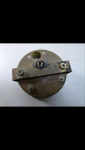
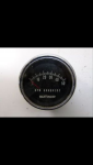
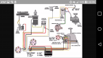
I've searched these forums and many others but can't find the info I need. I have a 1969 Mercury 650 Thunderbolt 4cyl. And the matching tachometer. I've just ordered the wiring harness that plugs into the Mercontrol but the back of the tach is no longer legible as far as the hookup. It is a 3 wire setup. Anyone have experience with these old tachs who can shed some light on the proper hookup? Thanks.
 

Attachments

  • Screenshot_2016-03-09-22-13-19.png
    Screenshot_2016-03-09-22-13-19.png
    880.6 KB · Views: 9
  • Screenshot_2016-03-09-22-13-11.png
    Screenshot_2016-03-09-22-13-11.png
    802 KB · Views: 6

Texasmark

Supreme Mariner
Joined
Dec 20, 2005
Messages
14,557
You don't want to guess. Usually 4 inputs:

Colors on more modern engines, maybe your's too:
12v red/purple/red with purple stripe
Ground (if you want to call that an input....actually return for 12v) black
Tach input signal from engine, grey
Dial light power...don't know color but would be common to all instruments in dash for a clue.

If the input isn't protected, getting the power leads reversed or putting power to the signal terminal could smoke the tach.

I think Teledyne made tachs for marine use....just Google marine tach hookup and find something that matches yours.

Or wait for a knowledgeable responder on here.
 

Chris1956

Supreme Mariner
Joined
Mar 25, 2004
Messages
27,137
I had thought the older Merc Tachs were two wire. However, that old tach likely requires 3 wires (+12VDC, Gnd, Signal), because it has (or had) the light feature.

Tracing the connections to the power and ground for the light will tell you part of the story, however, I would seek out an expert in those old tachs before connecting it.
 

merc850

Commander
Joined
Jul 7, 2010
Messages
2,026
The tach says Mercruiser and it only goes to 5000 rpm so I don't think it's for your motor - it's for a 4 cycle sterndrive. I would buy a new alternator driven tach and you can still use your control harness plug if you make a change in the wiring (see diagram) move the brown wire to a terminal on the rectifier that has a yellow wire (make sure you put the yellow wire back on) not the red one! wiring-diagramtachwire.jpg
 
Last edited:

Hammssammich

Cadet
Joined
Mar 9, 2016
Messages
14
Okay, So I've read all the posts about moving the brown wire from the Switchbox to the stator wire on the rectifier. Problem is all the schematics I've seen don't represent my Switchbox. It would seem its been replaced with another year perhaps. I've included a diagram that looks like my box. My question is since there is no brown wire would I be looking to the tan one here? I've run a continuity test from the tach control and get tone but also get tone from any grounded source. Dont want to blow this motor up.
Thanks in advance!
 

Attachments

  • Screenshot_2016-03-14-20-38-05.png
    Screenshot_2016-03-14-20-38-05.png
    1.1 MB · Views: 11

Hammssammich

Cadet
Joined
Mar 9, 2016
Messages
14
After more research it looks like what I thought was tan is in fact orange once the tape was pulled back. This is a kill wire I think. It pigtails in with the wire that is supposed to carry the tach signal just after they enter the cowl. This is getting confusing. They also shared a post on the Switchbox with the mercury switch if that helps at all.
 

Chris1956

Supreme Mariner
Joined
Mar 25, 2004
Messages
27,137
Orange (or Salmon) is the ign killer wire used on ADI (non distributor) ignition. It is unused on battery CDI distributor ignition.

In your diaghram, it looks like the tan wire on the engine harness connects to the brown wire in the boat harness. If that is true, it looks like the brown wire would get the correct tach signal, via the engine tan wire. Not sure why Merc did it that way. Did they run out of brown wire?
 

merc850

Commander
Joined
Jul 7, 2010
Messages
2,026
This is an unusual setup.
In the diagram for the motor harness E + G are connected - G is the Brown wire for the tach signal, you have to separate the E+G wires and connect G to one of the Yellow wires from the rectifier. I would do it in stages, separate the wires and see if the motor still starts and runs if yes then connect G to the Rect leads then touch the brown wire to the back of the tach to see if it's a go.
If you don't feel comfortable with this setup run a wire from the Rect to the "sender" terminal on the tach making sure that it is not vulnerable to damage. This is possibly your best option; after further study of the diagram.
 
Last edited:

merc850

Commander
Joined
Jul 7, 2010
Messages
2,026
After more thought I would not change any wiring in the motor but run a separate wire for the sender, you will still have a lighted tach that turns off with the key.
 

merc850

Commander
Joined
Jul 7, 2010
Messages
2,026
OK just run a wire from a yellow rect. terminal don't mess with the engine wiring.
 

Hammssammich

Cadet
Joined
Mar 9, 2016
Messages
14
So after some rigorous wire tracing and calculated risk vs reward thinking the tach is in and functioning as expected. Thank you for the help guys!
 
Top