Help with charging system?

nola mike

Vice Admiral
Joined
Apr 22, 2009
Messages
5,362
Had some fluctuating voltages last year after installing the new engine. Didn't stay very long, but would overcharge for maybe 30 sec, then undercharge. Took the boat out for the first time this season, and on the way out my voltage spiked to 18v for a minute before settling to 14.2. after a while it dropped to battery voltage (12.7) before getting back to 14.2. on the way home it charged for a while before again dropping to 12.6 for the rest of the trip. I thought it was the voltage regulator, but I swapped in a spare alternator and am still not charging. Engine starts and runs fine, and I'm getting 12.5v from the battery when running.
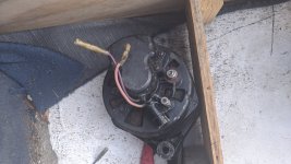
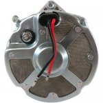
1. Just to make sure my wiring is correct: My old (I think original) alternator had a purple lead hooked to purple wire, and red wire connected to red wire. There was a B+ post for the orange wire and a separate ground stud. "New" alternator has red wire, which I connected to red, black wire that I connected to purple, B+ terminal, and a ground lug (I think) attached to the frame screws. I hooked red to red and black to purple.
2. When started, I'm seeing 12.xx at the red wire, and 11.xx at the purple.
3. I'm also seeing 24v (?) from the orange wire to engine ground with engine running.
4. I thought that would mean I'd have a problem with the 90a starter fuse, but with the engine off I get 12v at the orange wire. Access with a hot engine made testing more around the starter difficult.

I'm a bit frustrated so probably missing something obvious, but it seems like the alternator is both putting out too much voltage, but it isn't making it to the battery. Because of the symptoms, I originally just assumed that I had a bad regulator and didn't test the old alternator outputs before swapping.
 

dubs283

Vice Admiral
Joined
Jul 27, 2005
Messages
5,322
purple is sense, red is excite

voltages with key on should reflect what you are seeing, if your engine is equipped with points, the purple wire should be resisted, hence the difference in voltages. engine running voltages should be roughly 2 volts higher than static (non running) on each wire

24 volts from the orange wire to ground? orange wire should be connected to the battery lead at the starter, not ground. unless of course you are reading the voltage with your meter red on B+ stud and black on ground

the alternator may ground through the frame to the bracket but with a ground stud i would install a solid ground (if not already equipped) to the stud

24 volts output means wired incorrect or regulator is faulty
 

alldodge

Moderator
Staff member
Joined
Mar 8, 2009
Messages
42,056
Assuming your talking about the 86 Conroy 4.3

Seeing anything above 15V usually means the ALT sense lead is not connected to see battery voltage, or the regulator is bad. AS dubs mentioned, could be a grounding issue.
 

nola mike

Vice Admiral
Joined
Apr 22, 2009
Messages
5,362
Assuming your talking about the 86 Conroy 4.3

Seeing anything above 15V usually means the ALT sense lead is not connected to see battery voltage, or the regulator is bad. AS dubs mentioned, could be a grounding issue.
This has persisted through 2 alternators. The one I just installed worked fine when last used. So there was a bit of corrosion inside the female ends of both harness leads. I'm going to clean them off better now that I got the boat off a (bouncy) mooring. The thing that I don't understand is why am I seeing 24v from the orange wire when running, but it isn't making it to the battery? And again, I'm not sure which lead on the alternator is sense vs excite (black and red), and which engine wires are sense/excite (purple and red)

purple is sense, red is excite
Mercruiser manual has it the other way? red is sense and purple is excite. I'm not sure of the coloring on the alternator--I have a red and a black wire, not sure which is which.

24 volts from the orange wire to ground? orange wire should be connected to the battery lead at the starter, not ground. unless of course you are reading the voltage with your meter red on B+ stud and black on ground
Yes, that's what I'm doing.

the alternator may ground through the frame to the bracket but with a ground stud i would install a solid ground (if not already equipped) to the stud
There isn't a separate ground stud on the "new" alternator. There's a small lug attached to a case screw. I attached my harness ground to that.

24 volts output means wired incorrect or regulator is faulty
Again, doubt it's the regulator on 2 alternators (though possible). Trying to track down my wiring mistake I guess.
 

dubs283

Vice Admiral
Joined
Jul 27, 2005
Messages
5,322
right, got em mixed up.

red senses battery voltage (from red/pur lead) purple (ignition) is the excite

not sure if someone just installed a black wire in place of the purple on your alternator but swapping shouldn't hurt anything for testing purposes

24 volts from B+ but nothing at battery? should be a 10 ga wire directly from the stud to the starter post. continuity test may reveal an issue there
 

alldodge

Moderator
Staff member
Joined
Mar 8, 2009
Messages
42,056
If there is a bad connection and it looses a connection, it can blow the ALT real quick. The Sense and Excite can be connected together so long as they read Bat voltage.

That said, the excite would need to be disconnected to keep from draining the Bat when its off
 

bruceb58

Supreme Mariner
Joined
Mar 5, 2006
Messages
30,537
Do you have a picture of the wiring of your alternator we can see?

I put an answer on your other post. Assuming this is the same alternator that has the external regulator, switch to a new alternator with an internal regulator.
 
Last edited:

nola mike

Vice Admiral
Joined
Apr 22, 2009
Messages
5,362
not sure if someone just installed a black wire in place of the purple on your alternator but swapping shouldn't hurt anything for testing purposes
The black and red wires are pig tailed off the alternator

24 volts from B+ but nothing at battery? should be a 10 ga wire directly from the stud to the starter post. continuity test may reveal an issue there
24 volts from B+, 24v at far side of fuse (starter end of orange wire), battery voltage at the red wires going to the front end of the fuse with engine running. Battery voltage everywhere with the engine off.
Do you have a picture of the wiring of your alternator we can see?

I put an answer on your other post. Assuming this is the same alternator that has the external regulator, switch to a new alternator with an internal regulator.
My new alt looks the same as the stock pic below, and the other pic is the old alt. I'm going to keep on this thread, since I don't think I have a voltage reg problem at this point.

So bottom line:
1. My alternator appears to be working, as it's putting out 24v. I don't have my clamp on ammeter to test current, but I'm getting a lot (too much) voltage from the alt output.
2. I don't understand how I can get 24v to the alt side of the starter fuse, but it doesn't reach the other side with the motor running. I would say the fuse is shot, but I'm getting 12v at the alternator with the engine off. How is this possible? (I just realized that I didn't actually test the resistance across the fuse...duh, but still)
3. Also, the 24.x v was pretty much double battery voltage, FWIW.

IMG_20210523_191144_stock.jpg
adr0106_5__43636.1581603638.jpg
 

nola mike

Vice Admiral
Joined
Apr 22, 2009
Messages
5,362
Just tested across the fuse, I have continuity. This doesn't make sense.
Also forgot to mention that I did some voltage drop testing. The grounds are fine. With ignition off I'm not losing anything between the battery pos and alt orange. I'm losing a bit on the purple wire, but that's been a known problem at the helm. It's actually a lot better than it was before I replaced a corroded ignition fuse, so I don't think that's it, but possible. I guess I should tie the excite/sense wires together to rule that out.
 

Bt Doctur

Supreme Mariner
Joined
Aug 29, 2004
Messages
19,291
An alt puts out 14.6 PERIOD, not 24 unless your alt was made for a diesel application. Seeing anything over 14 v means the alt is not connected to the battery. With the motor off, do you see 12v at the alt output terminal?
 

nola mike

Vice Admiral
Joined
Apr 22, 2009
Messages
5,362
An alt puts out 14.6 PERIOD, not 24 unless your alt was made for a diesel application. Seeing anything over 14 v means the alt is not connected to the battery. With the motor off, do you see 12v at the alt output terminal?
Yes. And I'm for sure getting 24v at the output terminal when running. Measured with 2 multimeters and using different ground points. But not at the battery. I agree, this doesn't make a damn bit of sense for a few reasons. I wonder if I should disconnect the orange wire and just measure from the alt output terminal.
 

Bt Doctur

Supreme Mariner
Joined
Aug 29, 2004
Messages
19,291
not connected to a 12v source on the output lead will result in a runaway alt, connect the output to the battery and retest
 

nola mike

Vice Admiral
Joined
Apr 22, 2009
Messages
5,362
not connected to a 12v source on the output lead will result in a runaway alt, connect the output to the battery and retest
I figured if I still had a high voltage then I could rule out the alternator as the culprit--as it is it seems I have a runaway alternator. Are you saying just connect a new wire from the output terminal directly to the battery? I thought about that, but am a bit nervous about bypassing the 90a fuse.
 

Bt Doctur

Supreme Mariner
Joined
Aug 29, 2004
Messages
19,291
nothing to worry about for testing, if the alt now responds correctly then your 90a fuse link is bad. If it was good you would see 12v at the output post with the engine off
 

nola mike

Vice Admiral
Joined
Apr 22, 2009
Messages
5,362
nothing to worry about for testing, if the alt now responds correctly then your 90a fuse link is bad. If it was good you would see 12v at the output post with the engine off
I am seeing 12v at the output post with the engine off.
 

nola mike

Vice Admiral
Joined
Apr 22, 2009
Messages
5,362
Well, more weirdness today. Charged the battery overnight, and forgot to reconnect the sense and excite wires prior to starting. But hey, guess what? Alt immediately showed 14.9v at the helm at idle. So I reconnected both wires. No charging. Reconnected just excite wire. Charging. Just sense wire. Nothing. Several different combos that didn't work, then tried disconnecting both again, and it didn't charge. WTF. At least I think I've ruled out a wiring issue as my culprit. I bit the bullet and just ordered a new alt so that I can get on the water this weekend. There were many different ones available, and I couldn't find a reason why one would work and not another if it physically fit.
I ended up getting this one from db electrical because it has a tach wire output as well--I've been trying to get an electronic tach working, so hoping this might kill 2 birds. Can anyone confirm that this will or won't work?
 

alldodge

Moderator
Staff member
Joined
Mar 8, 2009
Messages
42,056
I'm thinking problem in the 10 pin engine connector or splice connection with the 50 amp breaker

Red from starter post to 50 amp
Red/Purple from 50 amp to 10 pin and ALT
Purple from 10 pin to ALT

Get an ohm meter and disconnect battery, then ring out the wires
 

alldodge

Moderator
Staff member
Joined
Mar 8, 2009
Messages
42,056
I also know that ALT from DB and have one sitting on the shelf (100 amp), its a piece of crud. Got a one wire and a connector to add Sense and Excite leads, and never did work correctly
 

nola mike

Vice Admiral
Joined
Apr 22, 2009
Messages
5,362
I'm thinking problem in the 10 pin engine connector or splice connection with the 50 amp breaker

Red from starter post to 50 amp
Red/Purple from 50 amp to 10 pin and ALT
Purple from 10 pin to ALT

Get an ohm meter and disconnect battery, then ring out the wires
I didn't do that, but like I said I did test voltage drop on everything and it was fine. I'm getting good voltage at the sense wire and ok at the excite (though apparently that isn't even needed). The rest of the electric system is fine. I guess we'll see when the new alt comes .
I also know that ALT from DB and have one sitting on the shelf (100 amp), its a piece of crud. Got a one wire and a connector to add Sense and Excite leads, and never did work correctly
Boo. I've used their starters in the past with success. They (and everyone else) have a million different alternators. Not sure what the difference is as long as dimensions are the same size aside from pulley and 1 vs 3 wire. I couldn't resist seeing if the tach output would work with new gauge, especially since all of the signal converters from the coil were arguing $100 anyways
 

alldodge

Moderator
Staff member
Joined
Mar 8, 2009
Messages
42,056
Recon I got nothing else to offer, wish I did. An ALT is a pretty simple device, apply 12V to S and Ex, rotate and so long as they are connected to the Bat being charged they work or they don't
 
Top