Help with 5.7L front motor mount bracket location.

skunkedskippy

Petty Officer 2nd Class
Joined
Apr 30, 2017
Messages
130
I just finished rebuilding my stringers and transom. Reinstalled my bell housing and inner transom plate. Looking for advice on getting the location for the front mount brackets. They are "L", or angle brackets, if it matters.

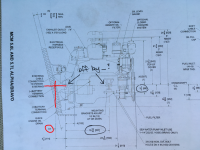
According to a diagram I found, the distance from rear-to-front mounts is 19-15/16" and the distance from the crankshaft centerline to bottom of front mounts is 3-1/2". I circled these numbers in the image below.

The crankshaft centerline also appears to be very close to the top of the rear mount surface, and bottom of the front bracket (that bolts to the engine), but not perfectly lined up.
IMG_6490.JPG

So the centerline doesn't seem to be perfectly inline with the top of the rear mount, or bottom of the front mount (arrows drawn above). Should I figure this into my measurements? If so, how much is it off by?

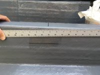
To get the rear-to-front location, I laid a straight edge along the rear mount holes, drew a line on the stringers and measured 19-15/16" forward from there.
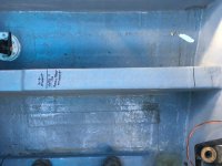
IMG_6485.JPG

IMG_6486.JPG

To get the the front mount bracket (or bottom of motor mount) height I laid the straight edge on top of the rear mount and measured 3-1/2" down. As mentioned above, if the centerline and mount are off by X", do I need to measure somewhere around 3-3/4" instead? Or is the difference small enough that the front mounts can be adjusted to make up for it?
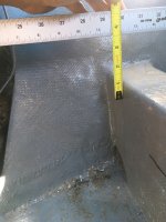
IMG_6483.JPG

Also, once I get the front mount height (marked towards the REAR, as I'm doing), what is an easy way mark it at the actual front location, where it will be bolted?

Once I get the locations dialed in, the plan is to bolt the front motor mounts and brackets to the engine, lower it down and thread the rear mount bolts, mark the front holes, lift it back out to drill the holes, and then back down for final installation. Now that I think about it, if I do it like this I might not even need to measure the rear-to-front distance.

Please let me know if there is a better/easier way to do any of this. I'm a newb if you can't tell.
 

Rick Stephens

Admiral
Joined
Aug 13, 2013
Messages
6,118
Paging @Rick Stephens , paging Rick Stephens will you come to the front office please :D

Bam. Called to the principal's office again.

Ok. Really easier than it looks. You are correct that there is a difference between the ear on the transom plate and the centerline of the motor. In all my measurements I called it a quarter inch and that worked out. In the end, the easiest measurement choice is to call the measurement from top of transom mount point to top of front motor mount on stringers an even 4 inches. A teensy bit extra is easily taken up with adjustments and if you gotta err, err to the short side since you can stick a shim plate under there if you had to. 4 inches works perfectly.

Next thing is, the important measurement is the 13 degree angle that the motor is DOWN from the transom. Matter not a wit what angle the transom is to the hull, no matter what, the motor is fixed at 13º down - always.

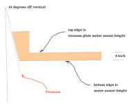
Knowing that, and knowing you need to be 4 inches under, I made up a jig to set height. That jig is pushed against the transom and pulled up to a straight edge across the transom mounting ears. Top edge is four inches above the bottom edge. Looks like this:

jig.jpg

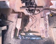
Here's a pic where my mounts were shaved off to match the jig.The jig is in the lower left, the angle I used to set the upper edge against is on the transom.

trimmed off.jpg

This will work for you.
 

skunkedskippy

Petty Officer 2nd Class
Joined
Apr 30, 2017
Messages
130
^This is absolute gold, thank you!

So the back angled edge of the jig butts up against the transom, and the vertical edge butts up to the BACK of the angle, top horizontal edge against the BOTTOM of the angle?

Also, the fiber washers are attached to my transom plate (I'd like to leave them attached so they don't fall out during motor installation. I assume I should add the washer thickness to the jig dimension?
 

Rick Stephens

Admiral
Joined
Aug 13, 2013
Messages
6,118
^This is absolute gold, thank you!

So the back angled edge of the jig butts up against the transom, and the vertical edge butts up to the BACK of the angle, top horizontal edge against the BOTTOM of the angle?
The vertical edge has no purpose. It gets ignored. I just made it narrow enough to fit behind the angle.


Also, the fiber washers are attached to my transom plate (I'd like to leave them attached so they don't fall out during motor installation. I assume I should add the washer thickness to the jig dimension?
Yes, you nailed it. Add the fiber washer to the 4 inches.
 

76SeaRay

Lieutenant Junior Grade
Joined
Aug 24, 2017
Messages
1,047
I am getting ready to replace the stringers around the engine bay so what I did was lift the engine into the boat, attached the rear mounts and adjusted the engine position so that the alignment bar would slide into the coupler. I have the advantage of having a gantry crane so that I could slowly adjust up and down as well as side to side. Once the alignment was correct, I shimmed the current stringers to get the front mounts positioned at mid travel. Now I can make some measurements to install new stringers as close as possible to the correct height for the motor mounts at mid travel. My old stringers were supporting a 70's vintage Windsor 351 and that mount is way different from the GM 5.7L that I am putting into the boat.
 

alldodge

Moderator
Staff member
Joined
Mar 8, 2009
Messages
40,754
When you do final alignment, the motor sits on the rear mounts with bolts in place just snug. The front of the motor is lifted just enough from the thermostat housing bracket so the bottom nuts can be run up against the bottom of the motor mounts, finger tight. The motor is lowered on to front mounts and the adjustments from there on moving both front mounts up or down equally
 

skunkedskippy

Petty Officer 2nd Class
Joined
Apr 30, 2017
Messages
130
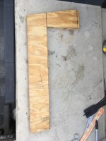
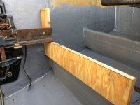
Finally had some time to play with this. Made my jig with the transom edge 13 degrees off vertical. Set everything up just as Rick described (I think).

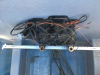
If I draw the line for my mounts across the bottom of the jig, it will not be parallel to the hull/stringer. It slopes up going towards the bow. Do my mount brackets need to follow this same slope?

IMG_6531.JPG

IMG_6533.JPG

IMG_6530.JPG
 

alldodge

Moderator
Staff member
Joined
Mar 8, 2009
Messages
40,754
Your using 13* but is your stern at 13*?
It could be anywhere from 10 to 16*

The mounts wind up where they a parallel with the gimbal bearing and drive. Need to try and be in the middle of the motor mount adjustment
 

skunkedskippy

Petty Officer 2nd Class
Joined
Apr 30, 2017
Messages
130
Your using 13* but is your stern at 13*?
It could be anywhere from 10 to 16*

The mounts wind up where they a parallel with the gimbal bearing and drive. Need to try and be in the middle of the motor mount adjustment
My stern is closer to 16. I got 13 from Rick's post, #3 in this thread. I'm a little confused now with the 2 different answers.

Could you elaborate a little more, please?
 

Rick Stephens

Admiral
Joined
Aug 13, 2013
Messages
6,118
Your using 13* but is your stern at 13*?
It could be anywhere from 10 to 16*

The mounts wind up where they a parallel with the gimbal bearing and drive. Need to try and be in the middle of the motor mount adjustment
No sir. All transom plates aim the motor 13º down from whatever the transom is. If the transom is 17º, then the motor is 4º up from the stringers. The transom angle is variable. The transom plate and gimbal housing set the angle of the motor the same no matter what - are not variable.
 

Rick Stephens

Admiral
Joined
Aug 13, 2013
Messages
6,118
Finally had some time to play with this. Made my jig with the transom edge 13 degrees off vertical. Set everything up just as Rick described (I think).

If I draw the line for my mounts across the bottom of the jig, it will not be parallel to the hull/stringer. It slopes up going towards the bow. Do my mount brackets need to follow this same slope?

View attachment 329302
You are exactly correct. The motor mount is at the angle shown by your ruler.

Rick
 

alldodge

Moderator
Staff member
Joined
Mar 8, 2009
Messages
40,754
No sir. All transom plates aim the motor 13º down from whatever the transom is. If the transom is 17º, then the motor is 4º up from the stringers. The transom angle is variable. The transom plate and gimbal housing set the angle of the motor the same no matter what - are not variable.

Where did you find this Rick. The install manual list transom angles can be 10 to 16 degrees and that angle is used to determine X dimension. Where not talking X dimension here, but if the transom can be at a different angle, then so can the plate
 

Bondo

Moderator
Staff member
Joined
Apr 17, 2002
Messages
70,525
No sir. All transom plates aim the motor 13º down from whatever the transom is. If the transom is 17º, then the motor is 4º up from the stringers. The transom angle is variable. The transom plate and gimbal housing set the angle of the motor the same no matter what - are not variable.
Ayuh,..... This is why I always just hang the motor, attached on the transom, align the gimbel/ coupler, 'n measure where I have to build the motor mounts out to from the hull,.....
 

Rick Stephens

Admiral
Joined
Aug 13, 2013
Messages
6,118
Where did you find this Rick. The install manual list transom angles can be 10 to 16 degrees and that angle is used to determine X dimension. Where not talking X dimension here, but if the transom can be at a different angle, then so can the plate
Every motor diagram shows the 13 degree angle. Full stop. Go grab a transom plate - look carefully at the center hole and the relationship to motor mount points below it. Both are exactly 13 degrees angled downwards from the back side of the transom plate - LOOK AT IT. Take a protractor to it if you have to, but it is 13 degrees.

That is the only angle that is fixed. The transom can be any angle within a small range - 4 degrees up or down from the 13º motor angle. If the transom was angled 13 degrees to the stringers then the motor would then be straight with the stringers. Every time.
 
Last edited:

Rick Stephens

Admiral
Joined
Aug 13, 2013
Messages
6,118
Ayuh,..... This is why I always just hang the motor, attached on the transom, align the gimbel/ coupler, 'n measure where I have to build the motor mounts out to from the hull,.....
I am a welder fabricator. Own my own shop with mills n lathes and every welder in the book. I live off drawings and accurate measurements. There is no friggin way that I am ever going to hang a hunk of metal and trim it to fit.
 

Rick Stephens

Admiral
Joined
Aug 13, 2013
Messages
6,118
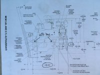
Make sure we are on the same page. This is the drawing from earlier in the thread. I scribbled in red. You will notice that 13º is fixed on the drawing. You will also note there is nothing fixing an angle to the hull. Will also note that the 13º angle downward on the transom plate to centerline of motor is an absolute. That is the only angle listed or important.

Another interesting point that isn't on this drawing is that where my two lines cross is exactly the center of the gimbal bearing. (+/- .125")


IMG_6490.png
 
Last edited:
Top