Help Please Newbie 1976 Mercury 850 Tilt Trim Wiring. Serial number 4425319.

JamesDunn

Recruit
Joined
Aug 17, 2020
Messages
5
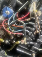
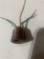
Gentlemen, I have spent hours working on the wiring for the tilt Trim. I had 2 switches. 1 at the transom and one next to the steering wheel. The one at the transom would move motor down but not up. The switch by steering wheel will go up but not down. I thought maybe the switch by the steering wheel was no good. I am at my wits end. I bought a new 3 prong switch and 3 new wires. I attached the red-blue and green wires exactly as shown in pic. Now I got nothing. I have fooled with this thing to a point I can’t think straight anymore. The green wire was from switch was attached to the green wire from the PLUG on the side of the pump. I just noticed there is another 0F2A3C17-B2DD-4B3E-A043-AE8D999B60BF.jpggreen wire coming off the back of the pump. I redid the red and black wires coming off the battery to the switch they are good. 10708599-8093-4278-8807-3210231ACB8C.jpegE5B2976D-1532-4A04-AAA3-0552AC9C894C.jpegI’m brain dead at this point. Could someone please tell me what I’m doing wrong. Very Frustrated.

0F2A3C17-B2DD-4B3E-A043-AE8D999B60BF.jpg
 

Chris1956

Supreme Mariner
Joined
Mar 25, 2004
Messages
27,653
It is very hard to see from your pictures, however, I had one of those units and am familiar with it. My unit had a single solenoid for up, and down was wired directly into a heavy duty switch. Your 3 amp toggle switch will not last long using it in the down direction. Both your switches should be 7A or greater, I would think. if you have the two solenoids, a 3A switch can work, I would think.

Those motors had a trim limit switch on the starboard trim cylinder. the switch was closed allowing Trim, for a while. You then needed to bypass the trim limit switch to allow tilt. This was done with a 3 button control panel. It appears that you do not have that feature. Also, those trim limit switches usually break. Look on the wiring harness, trace the wires from the starboard trim cylinder and see if the trim limit switch has been disconnected and jumpered. If not jumper them to eliminate the switch.

Each switch should have wires connecting to the up solenoid (blue), the down solenoid or motor wire (Green) (whichever you have) and power.

The source of these 3 wires is usually the 3 prong plug on the pump/reservoir. I would recommend you get the correct switches, wire one up and get it working, and then add the second switch, if you need it.
 

JamesDunn

Recruit
Joined
Aug 17, 2020
Messages
5
Ok looks like the trim limit wires were cut. See pic and by jumpered I’m not sure of this is it but please see 2nd pic. I hooked red,blue and green to the plug on the side of the pump and still nothing.
 

Attachments

  • 45B354F0-C3A1-43F4-8712-AC0DC77C9C84.jpeg
    45B354F0-C3A1-43F4-8712-AC0DC77C9C84.jpeg
    1.4 MB · Views: 5
  • 5F9532B0-8D2E-4FEF-BA09-587179525BEF.jpeg
    5F9532B0-8D2E-4FEF-BA09-587179525BEF.jpeg
    1.6 MB · Views: 5
  • D074AAA3-E5C0-4821-B329-F750319060C4.jpeg
    D074AAA3-E5C0-4821-B329-F750319060C4.jpeg
    1.3 MB · Views: 5

Chris1956

Supreme Mariner
Joined
Mar 25, 2004
Messages
27,653
I am not sure what those first 2 pictures have to do with the PTT system. Not sure what the first one is. The second one is the starter solenoid and switchbox.

The third one is the male plug for the PTT system. That should be attached to your PTT switch and plugged into the pump/reservoir unit. The PTT switch should be a single pole, double throw (SPDT), where the red wire goes to the common terminal on the switch.

The solenoid or solenoids for the PTT unit are mounted on the PTT unit. It is stand alone, as it was an option, really an add on to your motor.

The trim limit switch is an electrical switch. However, if you put voltage from the red wire to either the blue or green on that plug, and it is connected to the PTT pump/reservoir, and the PTT pump/reservoir is wired as from the factory, you will bypass the trim limit switch and the PTT system should function.

As a test, with the PTT system powered by the battery on it's standalone battery cables, jumper from the horizontal slot in the PTT pump/reservoir slot to one of the vertical slots. The motor should trim up or down. If not the PTT pump/reservoir has some issue.
 

JamesDunn

Recruit
Joined
Aug 17, 2020
Messages
5
I am not sure what those first 2 pictures have to do with the PTT system. Not sure what the first one is. The second one is the starter solenoid and switchbox.

The third one is the male plug for the PTT system. That should be attached to your PTT switch and plugged into the pump/reservoir unit. The PTT switch should be a single pole, double throw (SPDT), where the red wire goes to the common terminal on the switch.

The solenoid or solenoids for the PTT unit are mounted on the PTT unit. It is stand alone, as it was an option, really an add on to your motor.

The trim limit switch is an electrical switch. However, if you put voltage from the red wire to either the blue or green on that plug, and it is connected to the PTT pump/reservoir, and the PTT pump/reservoir is wired as from the factory, you will bypass the trim limit switch and the PTT system should function.

As a test, with the PTT system powered by the battery on it's standalone battery cables, jumper from the horizontal slot in the PTT pump/reservoir slot to one of the vertical slots. The motor should trim up or down. If not the PTT pump/reservoir has some issue.
The first picture is showing you the wires were cut on the trim limit switch on the starboard side. 2nd picture is 2wires on the starboard side of the motor I thought was where it was jumpered. Guess not. Third picture was just showing you the plug that plugs in on the side of the pump. I did attach the red, blue and green wires to the same color wires on the plug and plugged it in on the pump. Still got nothing. You have to dumb it down for me a little. As for this I haven’t a clue what you are telling me to do. As a test, with the PTT system powered by the battery on it's standalone battery cables, jumper from the horizontal slot in the PTT pump/reservoir slot to one of the vertical slots. (WHAT). Sorry I’m not at all familiar with these boats and wires. Now I hooked up the wires from the switch the red the green the blue to the plug on the side of the trim pump like you told me.I got nothing. Now what wires go to the single solenoid. I took the single solenoid off the bracket on the pump so I could see what and where I was installing the wires. All the PTT AND SPDT references throw me for a loop. Dumb it down please.
 

Chris1956

Supreme Mariner
Joined
Mar 25, 2004
Messages
27,653
OK, simple version. PTT is standalone system, not connected in any way to engine.

PTT pump/reservoir has it's own battery cables. Make sure these are connected and clean.

PTT motor is 3 wire type. The black wire from the motor should be connected to the PTT bracket. PTT bracket should be connected to battery negative cable.
Do you have 2 solenoids mounted on the PTT bracket or just one? I expect one.
Up solenoid will have battery cable on one large post, large blue wire to PTT motor on other large post, thinner blue wire on small post(from 3 prong female plug), and ground wire on other small post. Solenoid will be bolted to PTT bracket.

Down circuit, if one solenoid circuit, will have a terminal block connecting large green wire from PTT motor to large green wire from 3 prong female plug.

3 prong female plug will have battery power from solenoid, on red wire.

Connect red wire from male connector to center of SPDT switch. Connect blue wire from male connector to one post on switch and green wire to the other post on switch. When you connect male PTT connector to female PTT connector and toggle the switch, it connects battery power to one wire of the motor, via solenoid or directly, and PTT motor should run.
 
Top