Re: HELP! JANE! Stop this crazy thing! 62 Erude Lark 6
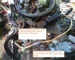
The vacuum cut-out switch is mounted on plastic, therefor not grounded. But the switch body is connected to the safety switch, which grounds at high throttle settings. That scheme does two things:
1. It prevents the motor from starting at high throttle settings
2. It prevents the vacuum cut-out switch from working at high throttle settings.
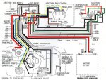
FYI: The diagram shows the coils labeled backwards. The upper cylinder coil is the one toward the front of the engine.
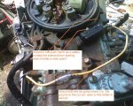
The safety switch that I have is reversed. at full throttle the switch (under the rear of flywheel) is NOT grounded. At low throttle the safety switch IS grounded. I tested it by setting multimeter to ohm, connected one meter test to screw on the head. Connected the other test lead to the back of the switch. checked meter and it did not show any continuity. When pressing the button on the switch I had a 0 ohm short.
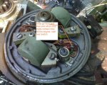
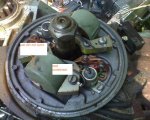
Now with that being said. When it is at full throttle the plate that should be striking the safety switch is pasted it. At current configuration the switch does nothing. I will have to adjust the plate so it will contact the button on the switch (no adjustment on the switch already checked it).
There were no leads coming off the points to kill the engine so maybe the PO turned that plate upside down or something.
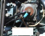
I notice on the switch there looked liked 2 places to connect the wire leading to the over-rev switch. One across from the word "open" and the other across from the word "close". But the one across from the word "close" looked as if it had been removed by the factory.
That bring around another question. How does safety switch work with the solenoid?
I know
1. the positive side of the battery goes one large stud of the solenoid.
2. The body of solenoid is grounded or connected to the negative side of the battery.
3. Then the other large stud of the solenoid there is a lead going to the starter.
4. There is also a small lead going to one small post on the solenoid that,
when energized, makes the two large studs kick in and sends power to the starter.
5. The other small post on solenoid is connected to the safety switch.
So if the small post connected to safety switch side of the solenoid sees a ground it will not let the solenoid send power go to the starter?
IS that right?
KillerKilgore
