Getting access to throttle lever TRIM SWITCH (Mercury 50 ELPTO 2003)

Joined
Feb 24, 2010
Messages
11
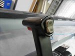
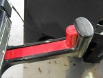
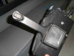
image_242811.jpg image_242812.jpg image_242813.jpg Hi all.

Hello all.

There's an old thread similar to this on here, but that guy sadly didn't receive a reply.

My throttle arm TRIM SWITCH (MERCURY 50ELPTO, 2003) is a bit ropey - the one on the cowl works fine, but the 'down' on the throttle arm works only intermittently. Also, it 'feels' a bit sloppy in action, and is not as crisp as it once was - so that's my main suspect.

I'd like to get the fellow out - except I don't know how to access to it...

Any ideas, please?

See photos: the upper section of the throttle arm has a one-piece plastic cover which I can just about partly prise up near its bottom as it goes around the arm and you can get to its ends where it meets the red 'neutral lock' lever, but I'm loath to prise it any further, and I cannot see how it can lift off the top handle part as it seems to fully cover this, all around.

Thank you.
 
Last edited:

CharlieB

Vice Admiral
Joined
Apr 10, 2007
Messages
5,617
That big squarish sticker on the bottom of the arm should peel off carefully so not to destroy it, and you may find the retaining bolt holding the arm on.
 
Joined
Feb 24, 2010
Messages
11
Many thanks, Charlie.

I've since been told how to do this from a guy on another forum.

Yup - that 'sticker' (in fact the whole plate) comes off.

First, tho', you need to remove the whole control unit - three nuts - from your console (the bolts pass through the control unit from the outside with the nuts inside the console).

Behind the removed unit, in the centre, you'll find the recessed head of a bolt which passes through the unit and goes into the handle and secures it.

Prise off that square cover - use a small flat-bladed screwdriver - and you'll see the ends of the switch wires as they disappear into the unit, and you'll also see the end of the bolt above.

Undo that bolt and the whole handle will come off. It'll be restrained by the cable tho'.

The red 'neutral lock' lever is held in with a small bridging clip and two screws. (Mine are still stuck so not yet removed...). When that red lever is removed, you should get access to the back of the trim switch screw. (Watch out - there will be a spring behind that red handle somewhere...!)

The back covers of the control unit are held on by 5 screws - 3 in the main part and two hold a narrower cover along the bottom. (Again, I still have one of these bar stewards to remove... :-( )

Once all that is removed, you should have access to the wiring 'push' terminals so will be able to remove the switch complete with short length of cable.

(I'm only half way through the job.... grrrrrrrrrrrrr)
 
Last edited:
Joined
Feb 24, 2010
Messages
11
Having now completed the job (actually finding that the wires are ok...), I'll add a couple of more points in case anyone else is doing this kind of job.

Ensure the gear/throttle lever is in the 'neutral' position before you remove the back covers (main cover has three screws, the lower one 2). I'm not sure how important this actually, is, but it's complex inside that unit so best to not add any unwanted variables!

Ok, the bottom panel will not come off by itself - incredibly, the top cover overlaps a segment in the corner, so the top cover has to come off (or be loosened a great deal) before the bottom cover comes off!

See the throttle 'fast idle' lever? Leave that in place when you remove the top cover - it'll come away with that cover, still attached to it. There's a very good reason why I'm suggesting this - the throttle lever and the main gear/throttle control are 'linked' via a small round spring-loaded bearing wheel (around 8mm dia) which ensures that the gear lever cannot be engaged when the engine is 'fast-idled' (you are probably aware of this feature). If you remove this fast idle lever, you will leave behind the mechanism with a wee pinion which does this safety job. Once you remove the cover - leaving this mechanism behind - the wee bearing wheel I mentioned before will move position (as it's spring-loaded) and you won't be able to simply replace that cover again!

But, it ain't a problem if this happens. Simply refit the idle lever mechanism (it's a round disc about 50mm dia with a pin sticking out the back) and the lever back on to the back cover - it's only two screws. Push that wee round spring-loaded bearing out of the way as you position the round wheel. Screw on the idle lever. That wee bearing is now in the correct place - pushing against the outside edge of the fast idle disc. (This will all be obvious when you look at it - honestly...)

With the fast idle mech now fitted on to the back cover, you'll now be able to refit the cover - but make sure that the pin on the fast-idle wheel is in roughly the right place to engage with the slotted lever inside the control box; a wee bit of fast-idle lever wobbling will make it locate.

Sadly I couldn't take photos as my hands were thoroughly covered in grease (I gave the insides a liberal coating) but there are exploded diagrams out there and I'll happily guide peeps through this issue if needed.
 
Last edited:
Top