Re: Force 85hp head bolt specs
It's the same...The pipe looking thing on the diagram on the right side actually represents the cylinder head.
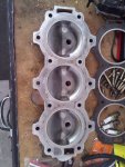
In your picture (post #16), the opening at the bottom (by the thermostat) is where the water enters the head after going through the thermostat. It flows through the head and exits at the opening at the top of your picture. From there it passes through a passage in the block and the adapter plate and goes out the exit hose attached to the exhaust cover (L-Drive).
Here is a picture of a 4 cylinder head assembly with the cover removed. Not sure if you were aware of the water passage in the head. Thermostat is located to the left in the picture. Water exit is the red arrow on the right. The cover is held on with three small bolts (3 cylinder) next to each spark plug hole (once you remove the head bolts). There is no gasket, just silicone RTV
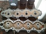
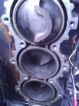
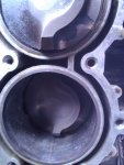
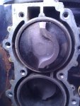
It surprises me that both you and Jerry have blocks that do not have the flow diverters. I've never seen one without them. I had always "assumed" that they were in all blocks. Now I'm questioning that "assumption". So I'm not 100% sure if they are actually necessary.
Regardless, I believe that you have found the reason why your motor was overheating. The broken impeller and bits and pieces of impeller blade in other parts of the water passages. I'm beginning to doubt that the lack of the flow diverters has anything to do with the overheating.
NOTE: If you decide to install the flow diverters....when I stated 1/4" line, I was referring to the "outside" diameter of the hose. When you go to the parts counter, and specify 1/4" hose, the parts person will be going by the "inside" diameter. It'll be too big. You have to explain exactly what it is you're looking for.


