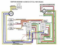
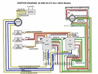
I've always been intrigued by this wiring diagram. All along I suspect there's a jumper between the blue terminals, hence the two blue wires were just crimped together and connected to one of the terminals. But then I also checked the 90 HP and it has basically the same wiring, two blue wires in 1 & 2 CD Module terminal.
The 85HP and 125HP motors of the same year and models are basically the same except that the 85HP has only three cylinders and uses three individual carbs. And the number of CD modules is also the same except that for the 3rd cylinder it uses only one circuit of the 2nd CD module. But if you check the stator blue wires on the 125HP, the two wires are independently wired on each blue terminal of each CD modules. Which makes a lot of sense in that each CD Mod requires each own power source from the stator. But with the 85HP, it doesn't look quite the same as the two blue wires are tied together and only seems (there might be a jumper, not sure) to be wired to the 1st CD mod.
So here's what needs to be investigated:
1. Check the resistance between the two Yellow wires coming off the stator (disconnected on both). Is resistance zero, meaning two wires are tied together on the same circuit? The two blue wires are tied together as it is already indicated by being crimped together. I'll surmised the two yellow wires are tied together, albeit at the stator end.
2. Is there a hard jumper wire between the two blue terminals on the terminal board? I surmised there is. Other members with 85HP can also verify this just to be sure. If there is, and yours is missing one, you can put in a jumper to make the 2nd CD Mod to fire or work.
Hi Jiggz,
I found a really interesting piece/write up from the late Frank that may answer both our curiosity (see below)
Re: 1988 Force 125 Negative Voltage CDI
If the flywheel is turning at about 300 RPM or better, the magnets generate an AC voltage of about 250 volts in each set of windings (there are two discrete sets of windings in addition to the alternator windings.) Since the windings are discrete, you need to be certain that a paired set is attached to a single box for best operation.
I have never tried it, but I suppose that an unpaired set would also work; the AC doesn't care where it is going, as long as it has a place to go. That's why on the three cylinder engines, the two blue stator wires are connected to the same terminal.
The positive half of the 250 or so volts AC charges one capacitor in the CD box. this services one cylinder. The negative portion of the sine wave charges the other capacitor. Thus: there is a positive and negatively charged capacitor in each box.
The trigger actually sets the timing and signals a switching transistor (with a low voltage) to dump the capacitor into its respective coil. This generates a sharp power pulse and a magnetic field in the primary coil winding. The power pulse drops off so fast that the magnetic field collapses through the secondary of the coil and generates 20-60,000 volts to fire the plug.
NOW: I don't know the exact mechanics of it but there is a ground wire for the CD box internals AND a separate ground wire for the kill circuit. Both CD boxes and all four coils MUST be grounded for proper operation. On the original black boxes, the kill wire is the white wire. Short it to ground and the engine stops. On some of the blue CD boxes, the kill wire is black with a tracer AND it is too short to reach the terminal board on the engine near the starter. So, it could be confusing and improperly connected.
If you use the wrong wire for ground, you will effectively be turning off that whole CD box.
SO: Since you did move CD boxes and since you did install a new one, you need to double check the wiring on the side terminal strip of the electronics mounting board, AND you need to be certain that you have a good ground from the mounting board to the block. I also like to "daisy-chain" a ground wire from each CD box and coil to a block ground. -- The electonics mounting plate is mounted on rubber vibration isolators and has no intrinsic ground, I just don't trust it.