Force 50HP running with cheap Honda 5 Pin AC CDI.

777funk

Petty Officer 2nd Class
Joined
Jan 12, 2015
Messages
150
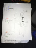
I accidentally shorted 12V to the trigger input on my top CDI. I considered replacing it but at $200 each, I thought... hmmm... as far as I know, it's just a basic AC CDI and coil. Timing advance is mechanical on these engines (not CDI electronic advance). I bet a Honda 5 pin (made for 50cc scooters) will run this thing. And after a rewire and removal of the original CDIs, it does work! I have no idea what WOT timing looks like on a light. I will have to take it out on a lake and check that as well as that both cylinders fire exactly 180 apart. But I have no reason to think that they do not. Is this a good idea? Maybe or maybe not. Probably not if a stock CDI is in good working condition. But at least a proof of concept. It didn't take long to test this. Maybe a couple hours wiring and a couple hours experimenting. I made up a wiring diagram and will post it after I clean it up a bit, but for now just a short startup video.
 

Jiggz

Captain
Joined
Oct 23, 2009
Messages
3,909
The main concern here is the operating voltages/temps of the Honda CDI. Do you happen to have the "White Paper" that lists all the operating characteristics of this CDI?
 

777funk

Petty Officer 2nd Class
Joined
Jan 12, 2015
Messages
150
The main concern here is the operating voltages/temps of the Honda CDI. Do you happen to have the "White Paper" that lists all the operating characteristics of this CDI?

That is a concern and I'm going only off of what I'd read from the Honda side of things (reported stator voltages). At this point, this only a science experiment until I have some hours of use. It seems it may be workable for my situation since I never go far from the boat launch and can usually fix things on the water if needed, but only time will tell.

The Force CDI seems to split the stator's 400VAC between the two CDI units (they are seeing the stator voltage in series I believe. I have no Force CDI schematic, but I believe they're feed in series since they each have one separate stator wire of the two coming from the stator). There is no way (aside from opening and modifying the Honda CDI) to 'split' the Force stator voltage by putting them in series since the 5 pin Honda unit shares grounds between the stator and trigger coils. To acomodate for this higher voltage, I originally made a voltage divider to knock it down to 60 VAC and this worked great. But it heated up the resistors (1 watt) way too much and was a mess from a wiring standpoint.

I don't really know what follows the stator wire inside the Honda CDI, but I would guess some sort of transistor based circuit that charges and discharges the capacitor... maybe MOSFETs. Supposedly the oldest most basic CDIs used a thyristor instead of transistors. So my guess is that the coil is seeing a near short circuit when the CDI is doing its switching. Thus the heat with the 1 watt resistors in my original voltage divider.

I now have 250 ohm 5 watt high power cement resistor in series with the stator coil feeding to each CDI. I did this for two reasons:
1. It will hopefully make life easier for the stator since I don't know what kind of load the original Force CDI put on the stator. I ran the engine for quite a while and no electrical components other than the resistors felt hot. So I would assume the stator and CDI are ok with what they're seeing.
2. It will reduce the voltage a bit for the CDI since the Honda stator put out 100-200VAC depending on who you ask (I've seen reported as low as 50v). It will run at 60VAC just fine as I confirmed. I am pretty sure most cheap high voltage capacitors are rated at 400VDC. So I wanted to be below this number in case that's what's inside the Honda CDI. I have seen the Force stator put out as much as 400VAC. Rectify that and you have around 560VDC. That wouldn't be good for the CDI's 400V caps (if that's what's inside). My resistor gives me a measurement at the CDI of around 200VAC with the engine running. Since Honda stators can put out this voltage, I'd guess this should be ok. Time will tell and I can easily carry a couple backups at $8 each for just the 5 pin CDI units (ebay honda aftermarket parts).

I should note that I'm not sure the power rating on my two resistors is high enough. It's very hard to calculate how much power is used since the duty cycle is very low (just short pulses). As the speed of the engine goes up this will change and more power will be going through the resistors feeding the CDI. I figure the easiest way to gauge the power rating for the resistor is to run it WOT for 5 minutes and feel it. The resistor gets hot, but not too hot to touch while idling. I'd guess 120F. A 10W resistor would be better of course and more than that would be better still. It may be possible to run it without the resistor at all, but I don't want to risk damage to the stator, (or a CDI failing due to over voltage). Obviously this is all just an experiment at this point. I'd by no means recommend it. But it will at least start and run the engine. I've reved it to half throttle and it sounds similar. I will also note that at half throttle I was seeing around 22 deg BTDC on my timing light that I monitored it with to make sure the CDI wasn't advancing timing. I don't believe it was advancing the timing from the trigger points.

Here's what I currently have wired up. I found that the polarity on the triggers is important. The pulse has to be polarized correctly for the CDI to fire. If the wires are switched on the triggers, it will not fire.
 

Attachments

  • IMG_1884_wiring_diagram_cleaned_up.JPG
    IMG_1884_wiring_diagram_cleaned_up.JPG
    2.2 MB · Views: 18
Last edited:

777funk

Petty Officer 2nd Class
Joined
Jan 12, 2015
Messages
150
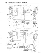
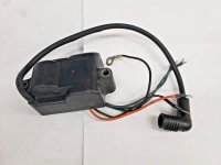
I should also post the original wiring for this engine for reference and to allow for color code correlation to the Force OEM ignition parts. My engine is the Pre-D model in the top half of the diagram. My two original CDI/Coil units are these ones.
 

Attachments

  • Force_50HP_electrical_diagram.jpg
    Force_50HP_electrical_diagram.jpg
    254.1 KB · Views: 17
  • force_50HP_Coil.jpg
    force_50HP_Coil.jpg
    143 KB · Views: 11

Jiggz

Captain
Joined
Oct 23, 2009
Messages
3,909
Very Interesting. Well, if you can make this work it'll surely be a welcome news for Force owners since original CDI's are just like you said very expensive.
 

777funk

Petty Officer 2nd Class
Joined
Jan 12, 2015
Messages
150
I just found a document from Vishay on finding the correct size (power rating) for a pulsed load carrying resistor.

This document says the relationship between continuous and pulsed is that quite a lot more power can be handled with pulsed loads (in some cases 1000x). Of course pulse shape and duration matters quite a bit. It's still a very complicated calculation. I'm going to watch the heat on the two resistors I have installed and do my best with the little data I have from that sheet and anything else I can find.

I'm thinking running the CDIs directly from the stator may or may not be good long term but I may just try it and see. I'm not too concerned about burning up CDIs since I can swap them out easily. I do not want to hurt the Force stator.
 
Last edited:

jimmbo

Supreme Mariner
Joined
May 24, 2004
Messages
13,463
Might be an issue regarding USCG Compliance, as I doubt an ignition for Scooters, was ever certified
 

Redbarron%%

Chief Petty Officer
Joined
Dec 7, 2017
Messages
479
Interesting. However you could also use the Mercury CDM modules as well.
Harnesses can be bought one Ebay to make the conversion.
However.
The issue with any of the CDI/CDM modules is the question of timing advance with RPM.
The difference in the Force/Mercury CDI and CDM is the trigger pickup and the application of bias voltage to correct for the increase of trigger voltage with RPM.
With the CDI the bias circuit is built in the CDI module(s) and with the CDM modules have the bias circuit built into the trigger coil itself.
What happens is with the increasing speed of the flywheel the voltage begins to increase sooner, advancing the timing as it reaches the voltage that triggers the CDM at perhaps 0.6 volts. To counteract this the bias circuit rectifies the pulses of the trigger and averages the voltage at any given RPM and subtracts that (taking into account the 0.6 volts needed to fire the module) to correct for the changing RPM.
So if you do not build a bias circuit be sure that you check the timing at max RPM and mechanical advance.
 

777funk

Petty Officer 2nd Class
Joined
Jan 12, 2015
Messages
150
Interesting. However you could also use the Mercury CDM modules as well.
Harnesses can be bought one Ebay to make the conversion.
However.
The issue with any of the CDI/CDM modules is the question of timing advance with RPM.
The difference in the Force/Mercury CDI and CDM is the trigger pickup and the application of bias voltage to correct for the increase of trigger voltage with RPM.
With the CDI the bias circuit is built in the CDI module(s) and with the CDM modules have the bias circuit built into the trigger coil itself.
What happens is with the increasing speed of the flywheel the voltage begins to increase sooner, advancing the timing as it reaches the voltage that triggers the CDM at perhaps 0.6 volts. To counteract this the bias circuit rectifies the pulses of the trigger and averages the voltage at any given RPM and subtracts that (taking into account the 0.6 volts needed to fire the module) to correct for the changing RPM.
So if you do not build a bias circuit be sure that you check the timing at max RPM and mechanical advance.
I didn't realize there was a conversion harness. I just saw $200 a pop used for Force CDIs and figured I'd try another route. These are $26 for a pair of CDIs, 5 pin plug wiring harnesses, and coils. The coils bullet connector into the CDI harness.

I put a light on it at idle (which I realize doesn't mean much) and it was actually a few degrees further retarded vs the stock CDI. I also looked at half throttle in gear with earmuffs and still no where near the 30 degree mark. I'd guess around 22 degrees BTDC. I need to check it on a lake at WOT to make sure I'm not ending up with an overly advanced condition. Also, I want to be sure both cylinders are 180 degrees from each other at WOT. Going to put a white dot on the flywheel opposite of 30 degrees and observe. I'll probably approach WOT with caution the first time. I'm thinking though that this is going to be less advanced vs stock and I will need to adjust the timing triggers ahead a few degrees for the new CDIs. I paid $200 for the whole boat, motor, and trailer. So it's not a huge risk. Still, it's useful so I'm of course going to be careful. I enjoy tinkering or I'd just have spent $200 on a replacement CDI/coil assembly. At the end of the day, a boat costs money! No way around that... lol.
 
Last edited:

777funk

Petty Officer 2nd Class
Joined
Jan 12, 2015
Messages
150
Update:
I took the boat out on the lake today and ran a near full tank of gas through it. I checked dynamic timing on both cylinders. They're both running 26 degrees before TDC on top and bottom cylinder (I made a mark equidistant to the #1 cylinder's 0 and 30 degree tick for the #2 cylinder and pulled the plug on both top and bottom cylinder to verify by piston travel that they were accurate). I have no idea if that's the same as stock since I never felt the need to check but power did feel similar. May be able to get a little more power by advancing 2-3 degrees. But as long as no issues with fouling etc, I'll probably just leave it there. It ran fine.

Based on this, I believe it's safe to say that these AC CDIs do not advance electronically. What goes in (via the mechanically advancing stock triggers) is pretty much what's coming out at the coils. There were no hickups with the new CDIs or coils. I will check the 5 watt resistors for any evidence of overheating and if so, put in 10 watt cement resistors in their place.
 

Jiggz

Captain
Joined
Oct 23, 2009
Messages
3,909
The manuals says, 30 BTDC at WOT. If you measured 26 at Dynamic timing, that is close enough although another two degrees will be better. Most Force outboard users recommend to retard the WOT timing, Static or Dynamic, 2 degrees from the manual not for speed but for the longevity of the piston and rings. I have not done it myself until I blew out two pistons last month. So this time around I'll retard it 2 degrees. And see if that'll make a difference.
 

777funk

Petty Officer 2nd Class
Joined
Jan 12, 2015
Messages
150
The manuals says, 30 BTDC at WOT. If you measured 26 at Dynamic timing, that is close enough although another two degrees will be better. Most Force outboard users recommend to retard the WOT timing, Static or Dynamic, 2 degrees from the manual not for speed but for the longevity of the piston and rings. I have not done it myself until I blew out two pistons last month. So this time around I'll retard it 2 degrees. And see if that'll make a difference.
I was really watching it and checked both cylinders. I didn't want to have a case where the engine linkage was advancing timing AND the CDIs were also advancing and end up with say 50 deg BTDC. So I was glad to see 26. That's probably costing me a few MPH speed. I should check it at 30 deg BTDC with a GPS vs how it is now to compare.

I don't mind a little less speed in trade for being easier on the engine. I didn't have a GPS with me yesterday, but I'd guess with a 16' boat filled to capacity with family, I was at 20-25 MPH. It felt like it always does with a full load. With only me in the boat, I can feel a big difference in hole shot and top speed. I used to have a Force 125 on an 18' and it was a lot less noticeable between one passenger and fully loaded. I miss the power of that 125, but it burned through the gas, that is for sure. I sold it before a move and miss that boat. It sold me on Force engines. I paid $200 in non running condition for that setup as well. It was well worth that. That's about the cost to rent a boat for an hour.
 
Last edited:
Top