Extending trim switch to engine cowel.

DunbarLtd

Petty Officer 1st Class
Joined
Nov 8, 2016
Messages
343
'88 Force 85hp. I am tired of having to use a stick to lower/raise the engine from outside the boat during launching/loading. I would like to add another tilt/trim switch near the stern. I am no electrician but me thinks I could run in parallel and simply add another switch or would it have to be like a 3 way switch in the house. Any help is appreciated.
 

The Force power

Commander
Joined
Feb 3, 2019
Messages
2,335
'88 Force 85hp. I am tired of having to use a stick to lower/raise the engine from outside the boat during launching/loading. I would like to add another tilt/trim switch near the stern. I am no electrician but me thinks I could run in parallel and simply add another switch or would it have to be like a 3 way switch in the house. Any help is appreciated.
Some models had a trim-switch @ the Cowl & you can just hook it in parallel
No need for additional wiring to Helm
 

DunbarLtd

Petty Officer 1st Class
Joined
Nov 8, 2016
Messages
343
There is already a switch at the helm already. I have to reach with a broom stick to hit the switch. No switch on the cowl. I want to add one near there.
 

jerryjerry05

Supreme Mariner
Joined
May 7, 2008
Messages
18,037
You'll need a 3 way and wire it to the existing wiring under the cowl.
The 87/88 started putting the relays and wiring under the cowl.
They make a heavy duty 3 way switch to handle the load(might need it????)
Remember Blue lead is for UP Green lead is for Down
 

The Force power

Commander
Joined
Feb 3, 2019
Messages
2,335
You'll need a 3 way and wire it to the existing wiring under the cowl.
The 87/88 started putting the relays and wiring under the cowl.
They make a heavy duty 3 way switch to handle the load(might need it????)
Remember Blue lead is for UP Green lead is for Down
Jerry, I think Dunbar meant a 3-way/pole switch set-up like in a house
A regular on/off/on spring loaded switch does the job, the switch controls the relays
 

jerryjerry05

Supreme Mariner
Joined
May 7, 2008
Messages
18,037
What I thought he asked for was putting in a switch in the cowl so he can tilt from the back of the boat.
 

racerone

Supreme Mariner
Joined
Dec 28, 2013
Messages
37,818
There should be lots of those switches on the used market.----E-bay is likely a good source.-
 

Jiggz

Captain
Joined
Oct 23, 2009
Messages
3,909
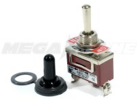
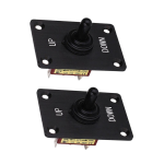
I installed one on mine. I used a three way toggle switch making it easy to install by drilling a hole on the upper portion of the lower cowling starboard side. The middle pole I connected the hot wire (red) and the blue and green on the other poles. The toggle switch is spring loaded meaning it always return to center position (off) when not activated or operated. For simplicity, the blue wire is activated when the toggle is pushed up and reverse for the green wire. The rubber cap came with the toggle switch keeps it water resistant. Here's a pic.
Toggle Switch T and T.jpg
 

DunbarLtd

Petty Officer 1st Class
Joined
Nov 8, 2016
Messages
343
I installed one on mine. I used a three way toggle switch making it easy to install by drilling a hole on the upper portion of the lower cowling starboard side. The middle pole I connected the hot wire (red) and the blue and green on the other poles. The toggle switch is spring loaded meaning it always return to center position (off) when not activated or operated. For simplicity, the blue wire is activated when the toggle is pushed up and reverse for the green wire. The rubber cap came with the toggle switch keeps it water resistant. Here's a pic.
View attachment 402941
This looks like it should work. If I may ask, how did you tap into the wiring? I understand the hot, blue, and green situation. I have a Force Service Manual that explains how the tilt/trim is wired. Just not sure where to tap into?
 

Jiggz

Captain
Joined
Oct 23, 2009
Messages
3,909
This looks like it should work. If I may ask, how did you tap into the wiring? I understand the hot, blue, and green situation. I have a Force Service Manual that explains how the tilt/trim is wired. Just not sure where to tap into?
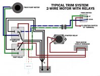
Here's a simple drawing. Tap within the engine cowling with the relays. You can use tap connectors like those used in automobile wiring or just "rat tail" it and taped off. In my case, I used about 24~30 inches of wiring, 14g- 3 wire SJOOW rubber PVC insulated cable. My switch is on the stbd side while the relays are on the port side. So the wiring went around the stern of the motor and back up to the stbd side. I used the black wire for the red hot, white for the blue wire and the green wire for the green. 14g wire is a little overkill since you're only controlling the relays coil and not the motor itself. So even 16g will work. But I already have some 14-3 wire so that's what I used.
T and T Wiring Tap Toggle Switch.jpg
 

jerryjerry05

Supreme Mariner
Joined
May 7, 2008
Messages
18,037
Trouble with that diagram is the power is from the ignition switch.
Needs to be ran from the power at the circuit breaker.
That way it has power all the time unless there's a battery switch??
 

Jiggz

Captain
Joined
Oct 23, 2009
Messages
3,909
Trouble with that diagram is the power is from the ignition switch.
Needs to be ran from the power at the circuit breaker.
That way it has power all the time unless there's a battery switch??
Follow the red line and it's coming from the ckt breaker straight from the battery. The blue and green wire are in parallel to the existing blue and green wires connected to the original T & T switch.

Even the original T&T switch at the control handle is not controlled by the ignition switch. Sure it is connected to the "B" terminal of the ignition switch but that "B" terminal is hot wire straight from the battery via a fuse or ckt breaker, if equipped.
 

DunbarLtd

Petty Officer 1st Class
Joined
Nov 8, 2016
Messages
343
How would you actually tap into these wires? Disconnect from relay. Remove crimp. Use a wire nut? Then crimp on another connector to slide into the relay?
Trouble with that diagram is the power is from the ignition switch.
Needs to be ran from the power at the circuit breaker.
That way it has power all the time unless there's a battery switch??
Yes... I ran the hot from the circuit breaker that the other "red" hots from the trim motor connect to. I tapped into the blue/white and green white wires just after (the relay side) the black plastic "butt connectors". Just stripped off a section of insulation and wrapped the wires around them and soldered and liquid taped. Seems to be working fine.

Only thing I think I need is a longer threaded switch because I used the one I had on hand which was the same as the helm switch and barely had enough threads but its snug enough for now. Otherwise the switch is working fine. Thanks for the help guys. Now I dont have to use a broom stick during launching/loading.
 

Jiggz

Captain
Joined
Oct 23, 2009
Messages
3,909
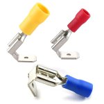
The picture I provided on the toggle switch you can get that from Amazon for cheaps. As for a professional looking connection use a Female Spade with Male connector (crimp type terminal). You put terminal on the new wire from the toggle switch. And then connect the existing blue striped or green striped wire to the male connector of this terminal and insert both to the relay. It looks like this
Spade Terminal with male connector.jpg
 
Top