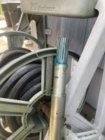
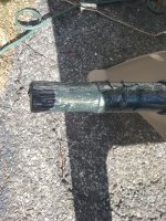
Engine alignment ,just got the tool. Pics posted

crazy charlie

Vice Admiral
Joined
May 22, 2003
Messages
5,500
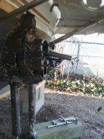
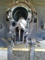
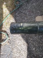
here is my original post: "1988 Regal commodore with twin 5.0LX rwc alpha drives. I needed to have an engine replaced last year.Found a 2003 5.0 Vortec and the marina that had it also did the install.Unfortunately the marina was not local and it was done in Feb so couldn't reply check it out till May.There is pretty strong vibration when the drive is engaged so I am assuming they didn't align the new engine.I don't think its something I can handle myself so my question is ,Can I have this done in the off season without running the boat??? I would like to try to get a mobile guy do this now but I still need the motor winterized for another 60 days or so.Thanks Charlie". So I just got the tool to check and I took some pics since I have never done this before.Im still gonna have an experienced tech do the alignment.took pics to see what you guys think.I applied the grease to the tool circumference wise so any friction points would be obvious.I pulled drive and it came off very easy as mine usually do from the abundance of grease.Charlie
 

Attachments

  • alignment tool side view.jpg
    alignment tool side view.jpg
    521.7 KB · Views: 37
  • alignment  tool rear.jpg
    alignment tool rear.jpg
    387.8 KB · Views: 37
  • alignment tool good side.jpg
    alignment tool good side.jpg
    1.8 MB · Views: 39
  • alignment tool friction side.jpg
    alignment tool friction side.jpg
    1.8 MB · Views: 38

alldodge

Moderator
Staff member
Joined
Mar 8, 2009
Messages
42,056
The only part of the bar that needs grease on it is the end, the last 2 inches. The end of the tool is not showing any marks from going in and other of the coupler. If its not going into the coupler then its not going to help, it has to be straight

First and second pic shows the bar angled down which tells me its no where near going into the coupler.

Second pic shows a lot of grease in the bellows, its better then water but still that's a lot. Stick your fingers in the center of gimbal bearing and rotate it some. If its not smooth as silk then it needs replaced
 

crazy charlie

Vice Admiral
Joined
May 22, 2003
Messages
5,500
The only part of the bar that needs grease on it is the end, the last 2 inches. The end of the tool is not showing any marks from going in and other of the coupler. If its not going into the coupler then its not going to help, it has to be straight

First and second pic shows the bar angled down which tells me its no where near going into the coupler.

Second pic shows a lot of grease in the bellows, its better then water but still that's a lot. Stick your fingers in the center of gimbal bearing and rotate it some. If its not smooth as silk then it needs replaced
Gimbal is very smooth, guess I over did it with the grease on ujoints but like you said ,better than water.I will give it another shot as I didn't think of the spline marks in the grease.I will climb into the engine compartment and see what I can see of the tool and coupler.My assumption was that the tool not being straight was a sign of misaligned engine.Wrong I guess but its my 1st rodeo with this particular maneuver.Thanks Charlie
 

04fxdwgi25

Chief Petty Officer
Joined
Mar 25, 2022
Messages
537
With bar removed, can you look inside, through the gimbal bearing, and see the engine coupler splines? Looks like the bar is missing the coupler splines completely and at that angle, you would never get the bar to insert into them.

Sometimes the gimbal bearing itself is out of alignment (it rotates and tilts within itself). In those instances, move the alignment bar (moving the gimbal bearing inner race) till it aligns with the engine coupling. That bar should be roughly in the center of the opening.

Sometimes it may take a nudge with a rubber mallet on the end of the bar to get the race to align. Alignment process calls for "thumping" end of bar in all 4 quardrents (12 oclock, 3 oclock, 6 oclock and 9 oclock) to assure centering when reading the "grease lines".
 

flashback

Captain
Joined
Jun 28, 2002
Messages
3,963
You didn't have the bar in far enough to engage the bearing or coupler. The grease on the larger segment of the bar would have been removed by the bearing.
 

nola mike

Vice Admiral
Joined
Apr 22, 2009
Messages
5,362
Agree with all of the above. Also, *very little* grease is needed on the end. It's more to see where the bar is rubbing than to actually lubricate anything.
 

crazy charlie

Vice Admiral
Joined
May 22, 2003
Messages
5,500
With bar removed, can you look inside, through the gimbal bearing, and see the engine coupler splines? Looks like the bar is missing the coupler splines completely and at that angle, you would never get the bar to insert into them.

Sometimes the gimbal bearing itself is out of alignment (it rotates and tilts within itself). In those instances, move the alignment bar (moving the gimbal bearing inner race) till it aligns with the engine coupling. That bar should be roughly in the center of the opening.

Sometimes it may take a nudge with a rubber mallet on the end of the bar to get the race to align. Alignment process calls for "thumping" end of bar in all 4 quardrents (12 oclock, 3 oclock, 6 oclock and 9 oclock) to assure centering when reading the "grease lines".
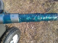
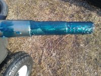
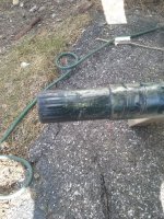
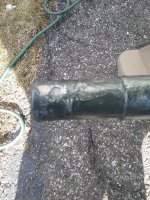
Ok so I totally messed up yesterdays attempt at using the alignment tool so I did it correctly today with pics.Looking into through gimbal bearing I was able to clearly see the coupler splines.Gimbal bearing moves smooth as silk.The alignment tool angle of the previous pics was badly exaggerated by #1 not having the tool fully inserted in the coupler, #2 having a huge pitch bow to stern blocked up for total bilge draining. #3 bell housing flexing slightly upward from lack of weight without a drive mounted. That being said ,I inserted the alignment tool properly and gave it a thump to be certain.Carefully pulled it out and inspected (did this 5 times) showing spline marks in the grease clearly on the bottom and stbd side of the tool. The top of the tool showed heavy friction and the port side showed fresh unscaved grease, not friction or spline marks.Crappy day for pics but I did the best I could
 

Attachments

  • alignment spline.jpg
    alignment spline.jpg
    643.8 KB · Views: 30
  • alignment spline2.jpg
    alignment spline2.jpg
    939.4 KB · Views: 30
  • alignment rub.jpg
    alignment rub.jpg
    901.9 KB · Views: 30
  • alignment rub2.jpg
    alignment rub2.jpg
    993.8 KB · Views: 30

Lou C

Supreme Mariner
Joined
Nov 10, 2002
Messages
12,655
In the 1st 2 pics it looks like the tool didn’t go all the way into the coupler, more like about half way.
 

04fxdwgi25

Chief Petty Officer
Joined
Mar 25, 2022
Messages
537
Good progress.... Heavy marks on the bottom indicate the engine is low in the front and the mounts need to be adjusted UP. Adjust engine to move opposite of marks. Then go from there. Can be a long, sometimes painful and frustrating, process of small adjustments, especially if doing it alone. But in the end, you will appreciate how smooth it runs afterwards.

Should be able to insert the bar all the way in with only finger pressure. (pulling back out can be a little more difficult, due to grease causing a suction on it)
 

crazy charlie

Vice Admiral
Joined
May 22, 2003
Messages
5,500
In the 1st 2 pics it looks like the tool didn’t go all the way into the coupler, more like about half way.
The tool def bottomed out on something,I heard a thud when pushing it in and I did this several times.Charlie
 

crazy charlie

Vice Admiral
Joined
May 22, 2003
Messages
5,500
Good progress.... Heavy marks on the bottom indicate the engine is low in the front and the mounts need to be adjusted UP. Adjust engine to move opposite of marks. Then go from there. Can be a long, sometimes painful and frustrating, process of small adjustments, especially i
I think you may have it backwards..?? The clean spline marks were on the bottom and stbd side of the tool and the heavy friction mark was on top of the tool with little to no friction or spline marks on port side of tool.Charlie
 

dubs283

Vice Admiral
Joined
Jul 27, 2005
Messages
5,322
Once the tool end enters the coupler snout it may require a hammer to fully seat the tool end in the coupler. Once seated fully you hammer the tool end up, down and side to side to align the gimbal bearing

Then remove the alignment bar and inspect the grease witness marks to determine which way the engine goes for full alignment

Merc manual states the tool should slide in and out of the coupler using two fingers. Very little force should be needed on a properly aligned engine. IME thus holds true for some engines but have found engines that are aligned properly based on witness marks but require more than two fingers to install and remove. Basically speaking you should not have to use a hammer to remove the tool. ymmv
 

crazy charlie

Vice Admiral
Joined
May 22, 2003
Messages
5,500
Once the tool end enters the coupler snout it may require a hammer to fully seat the tool end in the coupler. Once seated fully you hammer the tool end up, down and side to side to align the gimbal bearing

Then remove the alignment bar and inspect the grease witness marks to determine which way the engine goes for full alignment

Merc manual states the tool should slide in and out of the coupler using two fingers. Very little force should be needed on a properly aligned engine. IME thus holds true for some engines but have found engines that are aligned properly based on witness marks but require more than two fingers to install and remove. Basically speaking you should not have to use a hammer to remove the tool. ymmv
I guess I can take another whack at it...Pun intended...Charlie
 

04fxdwgi25

Chief Petty Officer
Joined
Mar 25, 2022
Messages
537
I think you may have it backwards..?? The clean spline marks were on the bottom and stbd side of the tool and the heavy friction mark was on top of the tool with little to no friction or spline marks on port side of tool.Charlie
OK, must have read it wrong.
 

crazy charlie

Vice Admiral
Joined
May 22, 2003
Messages
5,500
What ever you do, do NOT hammer the bar in. Hammering is only for side to side. I use my hands and just smack it all around. If its hammered IN it can get stuck
No hammers for this guy EVER on the boat. An

occasional wood block but no hammer.Now on brake rotors ????
Different story....
 

04fxdwgi25

Chief Petty Officer
Joined
Mar 25, 2022
Messages
537
Correct.... Front of engine goes opposite of heavy witness marks on the grease.
IE: Heavy marks on top, front engine mounts go down..
 

crazy charlie

Vice Admiral
Joined
May 22, 2003
Messages
5,500
Correct.... Front of engine goes opposite of heavy witness marks on the grease.
IE: Heavy marks on top, front engine mounts go down..
ok thanks so front meaning side where ps pump and belts are.....and what do you make of the no spline marks on the port side? One of the 2 mounts need to be moved down more than the other??
 
Top