Dual battery shut off wiring

Jakem

Ensign
Joined
Apr 25, 2021
Messages
964
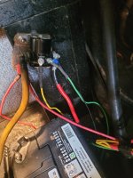
I want to install a shutoff and have 2 batteries hooked up. One starting and second for fishfinder and such. Not a clue how to wire it up
 

Jakem

Ensign
Joined
Apr 25, 2021
Messages
964
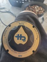
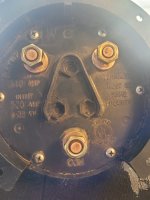
Here's what I got
 

Attachments

  • 20220707_173107.jpg
    20220707_173107.jpg
    1.6 MB · Views: 11
  • 20220707_173118.jpg
    20220707_173118.jpg
    2 MB · Views: 11

zellerj

Petty Officer 2nd Class
Joined
Dec 13, 2017
Messages
136
Google wiring a marine 1, 2, both switch with two batteries, and you will find what you want.
 

Jakem

Ensign
Joined
Apr 25, 2021
Messages
964
Seems I can only find for outboard engine. I've yet to see one that makes sense or including the starter solinoid
 

achris

More fish than mountain goat
Joined
May 19, 2004
Messages
27,468
I want to install a shutoff and have 2 batteries hooked up. One starting and second for fishfinder and such. Not a clue how to wire it up
If you want to dedicate a starting battery to the engine and a deep cycle to the rest of the system, then you are going to need something that allows both batteries to be charged from the engine and yet only the starting battery to actually have power drawn for cranking.

I've never looked into that in a marine environment (I just use 2x marine N70ZZ batteries and dual battery switch), but in the 4WD community, that's very common. I believe Redarc make an isolator specifically for that purpose. You'd need to check that it's SAE-J1171 rated though...

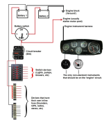
To use that switch you have, you'll need two batteries the same, and wire the boat like this....
1657264729552.png
 
Last edited:
Joined
Mar 27, 2010
Messages
3,008
What Achris mentioned is called an automatic charging relay. I have a couple made by Blue Sea Systems # 7611. Blue Sea charging relay I also have one in my work truck under the hood. We have added a 2nd battery and inverter by the back of the truck. With it, with the truck off, the two batteries are disconnected from each other, and cannot draw from the other without the engine running. It prevents the house electronics from drawing down your starting battery. As soon as a charge is put to either battery, something like 13 volts, both batteries are automatically connected together for charging. The thing that's good about it is it's fully automatic, you don't have to worry about switching the manual switch back and forth through out the day.

With the manual switch in Achris' diagram, either battery can power the load on "both" or both batteries can be used to start the engine if you have a weak starting battery. The manual switch will work great but the negative about it is you have to mess with a switch through out the day, and if you forget to switch it off "both" when you shut down the engine, you can potentially kill both batteries from the load of the electronics on the "house side".
 
Last edited:

achris

More fish than mountain goat
Joined
May 19, 2004
Messages
27,468
..., and if you forget to switch it off "both" when you shut down the engine, you can kill both batteries from the load of the electronics on the "house side".
I leave both batteries on, all the time, even at home. That's because when I get home, a trickle charger gets hook on and both batteries are maintained at optimum voltage at all times.

But yes, the device Eric is referring to (ACR) is what I had in mind.

Chri.....
 

Lou C

Supreme Mariner
Joined
Nov 10, 2002
Messages
12,686
If you have the simple 1,2,1+2, & off switch you can alternate the use of batteries to make sure each one gets charged. I use #1 on odd days #2 on even days. With this system if you leave it on both yes it can cause one bad battery to drain the other. In this case I’d use both only if either battery or both was too discharged to start the engine. The auto charging relay does not require thinking about this but I do think it’s a good idea to have individual battery voltmeters. We installed a dual battery system with an ACR in my brother’s Honda UTV & it works great with the dual volt meters you can watch it do it’s thing.
 

Jakem

Ensign
Joined
Apr 25, 2021
Messages
964
That diagram looks exactly like my dash. Makes sense now thank you
 

Jakem

Ensign
Joined
Apr 25, 2021
Messages
964
Aside from the solinoid. How does that play into this. Sorry if I'm missing something here
 

Lou C

Supreme Mariner
Joined
Nov 10, 2002
Messages
12,686
Just to add to that, the only thing that should get battery power with the switch OFF is the bilge pump/auto bilge switch. This is particularly important for boats left in the water in slips or moorings. I used to have my auto bilge switch hooked up to the common terminal and had to leave one battery ON when the boat was left on the mooring. What happened a couple of times was that I left the radio on, or another time I had my GPS/plotter set up for auto on (it would turn itself on, if it cut out after starting the engine) and it was running batteries down. So, I changed the settings in the GPS and have the auto bilge hooked up to #2 on the switch (there is a way to hook it up to both batteries using diodes, I have to figure that out one of these days). Now I can turn the batteries OFF when leaving the boat on the mooring, no more worries about dead batteries.
Its a good idea if you have chronic run down batteries to do a parasitic draw test. The GPS turning itself on was a real surprise to me! Boats unlike cars, are often wired so just about everything works with the key off except anything on the ignition circuit.
 

Jakem

Ensign
Joined
Apr 25, 2021
Messages
964
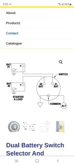
This is the unit I have. I don't understand the alt going to common and then the arrow. I'm a horrible electrician please help
 

Jakem

Ensign
Joined
Apr 25, 2021
Messages
964
Here it is
 

Attachments

  • Screenshot_20220708-150251_Chrome.jpg
    Screenshot_20220708-150251_Chrome.jpg
    290.3 KB · Views: 10

achris

More fish than mountain goat
Joined
May 19, 2004
Messages
27,468
I have no idea why they show an alternator connection right at that point. On all MerCruiser wiring the alternator connects to the main lead post on the starter solenoid, which is electrically exactly the same point as your diagram anyway...
 

Lou C

Supreme Mariner
Joined
Nov 10, 2002
Messages
12,686
On most inboard engines the common simply goes to the large positive terminal on the starter solenoid & there is usually another wire that goes from that terminal up to the B+ terminal on the alternator. If yours is wired this way then no need to add additional wiring. That Cole-Hersee switch is an excellent unit, very well made.
 

Jakem

Ensign
Joined
Apr 25, 2021
Messages
964
Here's solinoid...left post is positive to batt..then s terminal..then I...then starter
 

Attachments

  • 20220708_095842.jpg
    20220708_095842.jpg
    1.6 MB · Views: 6

achris

More fish than mountain goat
Joined
May 19, 2004
Messages
27,468
'S' = start. That's the wire from the start position on the key. That 'pulls' the solenoid.
'I' = ignition. That's the wire that give full 12v to the coil while you're cranking the engine.

That solenoid must be mounted to the engine block, or a black wire must be installed between the mounting of the solenoid and the engine (or it ain't gonna work).

Chris
 

Jakem

Ensign
Joined
Apr 25, 2021
Messages
964
I do have a wire hooked to the body of it however I had it going to neg terminal
 

achris

More fish than mountain goat
Joined
May 19, 2004
Messages
27,468
I do have a wire hooked to the body of it however I had it going to neg terminal
Battery negative terminal and the engine block are (electrically) the same thing...
 
Top