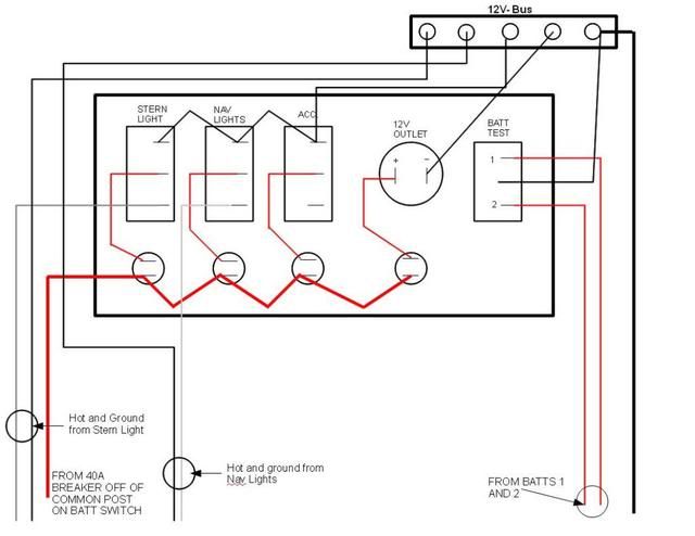
I have done a complete tear-down and restore of my 1986 Tracker and I'm finally nearing completion. Leaving for Michigan this Friday and would love to have my rig in-tow so this week is do-or-die time. Everything is pretty much done, except for the electrical system.
I purchased a 4 switch fuse block to replace the original. I will be powering a Nav light, Anchor light, Blige, and Aerator. Based on all the reading I've done using the search function, I think that I understand what needs to happen here, but perhaps a question or two.
The Postive from the Fuse Block to the Positive of the Deep Cycle and the Negative of the Fuse Block to the Negative of the Deep Cycle.
The Positive from each accessory listed above to the positive of its respective switch on the panel.
Where does the negative from the accessories go to? The fuse panel I bought does not have the built-in ground buss like the one that Silvertip (I think) posted in a similar topic. So do I purchase a separate ground buss and run them there? If so, how does the ground buss get wired? Just another run from Negative of batter to the ground buss?
I also have a fish finder that has it's own in-line fuse which will be wired directly to the battery and not through the fuse block.
So, depending on the answer of the ground buss, I would have 3 Positive and 3 negative leads to the battery (Trolling motor, Fish finder, Fuse Block)?


