Do I need diodes or should I run a relay for trim switch

KnightNight

Seaman Apprentice
Joined
Apr 2, 2021
Messages
49
I am trying to install a trim switch for the steering wheel instead of using the two-way toggle switch that came with the trim kit.

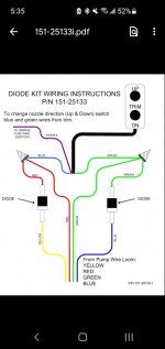
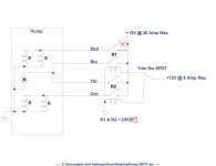
There is a diode kit supposedly you can use as below but I feel like a relay would be better solution? The pump is rated for max 20A for 12v circuit.

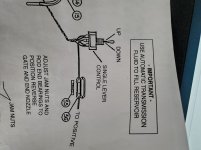
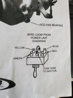
There is a 4 pin coming from the trim pump that is suppose to be used for control and mounts to a included toggle switch per diagram below. The Trim steering wheel kit is 3 wire only. (up/down/common).
 

Attachments

  • Screenshot_20210411-053600_Drive.jpg
    Screenshot_20210411-053600_Drive.jpg
    55.9 KB · Views: 20
  • 20210409_145206.jpg
    20210409_145206.jpg
    160.8 KB · Views: 19
  • 20210409_145152.jpg
    20210409_145152.jpg
    108.2 KB · Views: 19

jhande

Chief Petty Officer
Joined
Jun 26, 2010
Messages
442
I don't know anything regarding trim kits.

A diode and relay function totally different than each other.
A diode only allows the electrical current to flow in one direction.
A relay is activated from a low power source to allow a higher power source to feed the main circuit.

Does the trim motor operate by reverse polarity?
If yes then the diodes make sense over a relay.
 

KnightNight

Seaman Apprentice
Joined
Apr 2, 2021
Messages
49
I don't know anything regarding trim kits.

A diode and relay function totally different than each other.
A diode only allows the electrical current to flow in one direction.
A relay is activated from a low power source to allow a higher power source to feed the main circuit.

Does the trim motor operate by reverse polarity?
If yes then the diodes make sense over a relay.
I have no idea how it operates besides the first picture diagram showing the 4 pin wires coming from it. I would assume 2 for Up (red potential)/ 2 for down (green potential). There is a separate 1 wire ground on the pump also.

The diodes appear to keep the purple (potential for trim 3 wire) from backfeeding the pump?
 

jhande

Chief Petty Officer
Joined
Jun 26, 2010
Messages
442
I have no idea how it operates besides the first picture diagram showing the 4 pin wires coming from it. I would assume 2 for Up (red potential)/ 2 for down (green potential). There is a separate 1 wire ground on the pump also.

The diodes appear to keep the purple (potential for trim 3 wire) from backfeeding the pump?
I just did a quick Google search. The trim motors seem to work on reverse polarity.

This might help -
 

sam am I

Commander
Joined
Jun 26, 2013
Messages
2,169
I am trying to install a trim switch for the steering wheel instead of using the two-way toggle switch that came with the trim kit.

There is a diode kit supposedly you can use as below but I feel like a relay would be better solution? The pump is rated for max 20A for 12v circuit.

There is a 4 pin coming from the trim pump that is suppose to be used for control and mounts to a included toggle switch per diagram below. The Trim steering wheel kit is 3 wire only. (up/down/common).
Guessing the pump type is similar to or is a Bennett type pump? e.g., The red and green wires go to the hydraulic valve solenoids on the motor's front and both the blue and yellow wires go to the motor drive windings?

So, yes sure, you can use solenoids and wire it such that your push button switch controls relays which in turn runs the valves and motor......That is if you think the push button switch won't handle the current? That would be my only concern........The pump is rated for "20A max", but does the switch have a current rating stamped on it? The switch should equal to the pump or be greater I reckon........

If you do decide to use relays, you'll have two options,

1) Use two SPDT relays keeping the diodes setup and wire the pump wires to each relays NO contacts.........**Diodes ARE required when each of the two pump wires (red with yellow and green with blue) are connected together.

2) Use two DPDT relays and dump the diodes and wire the pump wires like they do with and as the toggle switch shows.

If you need a sketch of either or both let me know, I can scratch something out, it's not too complicated..
 
Last edited:

sam am I

Commander
Joined
Jun 26, 2013
Messages
2,169
***So, yes sure, you can use solenoids and wire***

Correction........"So, yes sure, you can use RELAYS and wire....."

Also

***The switch should equal to the pump or be greater I reckon***

Addition......"The switch AND THE TWO DIODES/wires should equal to the pump or be greater I reckon........"
 
Last edited:

KnightNight

Seaman Apprentice
Joined
Apr 2, 2021
Messages
49
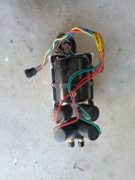
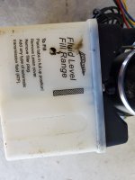
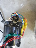
Here is what the pump looks like. 4 wires (2 to solenoids, 2 for switching the solenoids (power), 1 black ground). The lead connects to 4 pin 15ft length wire harness that can run up the dash.

This i the 3 wire control switch.

So my options would be?
1. Two SPDT relays + diodes
2. Two DPDT relays, no diodes.

Seems a lot easier to source marine rated SPDT relays and use diodes also.

This the diode kit:

There is a topic about a banderlog relay kit (mostly plug and play) that got rid of the diodes (I assume some kind of DPDT setup) but that website is gone now.


Attachments

  • 20210414_085953.jpg
    20210414_085953.jpg
    1.7 MB · Views: 6
  • 20210414_090012.jpg
    20210414_090012.jpg
    1 MB · Views: 6
  • 20210414_090104.jpg
    20210414_090104.jpg
    1.5 MB · Views: 8

jhande

Chief Petty Officer
Joined
Jun 26, 2010
Messages
442
The video I posted should point you in the right direction.
 

KnightNight

Seaman Apprentice
Joined
Apr 2, 2021
Messages
49
I watched the video, seems straight forward. I am still confused if I need diodes also with the two relays?

It seems to make the blue input (30 relay connection input) I would need a diode to combine green + blue then connect output wire to the input 30 terminal on the relay. On the second relay, I would do red + yellow then connect output to the input 30 terminal on the other relay?

Any idea what size diode or should I just buy the $30 diode kit?

Also I only assume 20A because that is what the factory fuse kit came with. I don't see any amp ratings on the pump itself, it is a Bennett.

edit: I understand Sam AM I I think now. I do need diodes for SPDT relays or just go DPDT relays. It seems DPDT relays are harder to find though for marine enviroments, diodes increase resistance so not as fast trim movement though.
 
Last edited:

gm280

Supreme Mariner
Joined
Jun 26, 2011
Messages
14,604
Haven't searched anything concerning your setup, so I am not offering any ideas towards that wiring. However, any time you use relays, it is always great practice to use diodes parallel with the relay coils. The anode connects to the ground side, while the cathode (banned side) connects to the positive side of the coil. This protects the relay, and any other thing in such relay drive circuits, from back EMF flow. JMHO
 

sam am I

Commander
Joined
Jun 26, 2013
Messages
2,169
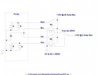
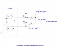
That trim switch looks to be a lower current type that is basically designed to drive trim relays, don't think I'd drive the pump directly with it.....

So yes, use a relay set up with that type of switch. If it were me, I'd drop using *diodes all together and just use two DPDT's, one (or two) less things to go bad ya know..........


gm280 mentioned above "protection" diodes across the rely coil (not shown), Yes always a good idea, agreed 100%......I don't see them being too critical here in this specific app., HOWEVER some relays manu's offer them built in......GET'UM if you have the option, BUT I wouldn't worry horribly if you do have them.

* These diodes in this config are "current steering".........More on that in a later episode
 

Attachments

  • Pump DPDT.jpg
    Pump DPDT.jpg
    133.3 KB · Views: 15
  • Pump SPDT.jpg
    Pump SPDT.jpg
    133.2 KB · Views: 12
Last edited:

KnightNight

Seaman Apprentice
Joined
Apr 2, 2021
Messages
49
Last edited:

sam am I

Commander
Joined
Jun 26, 2013
Messages
2,169
You're quite welcome, let us know how she works when it's up and running?
 

KnightNight

Seaman Apprentice
Joined
Apr 2, 2021
Messages
49
Sure, I have been replacing almost everything mechanical in this early 80s jet boat. I added a trim diverter as an upgrade, hence my reason to add this trim pump.
 
Top