Diode installation on 1972 Rude CD Ignition

Joined
Jul 12, 2023
Messages
29
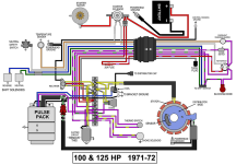
Can someone please show me where the diode is supposed to be installed to eliminate the voltage drop to the CDI pulse pack as indicated by Joe Reeves for 1972 Model Number 100293R 100hp (with Hall Effect Sensor)??

I have spark at the ignition coil but not to the plugs in the cylinders..

The starter solenoid has 4 terminals going from top to bottom with the solenoid attached to the block my engine is laid out as follows…

Top Large terminal - (+) from Battery & a 2-wire group (one is looped and used to contain a 20amp fuse which was deleted by previous owner) (The other leads to the terminal board, I installed the diode right before the terminal block in that red power wire that connects to the terminal block from the solenoid top terminal, I am not sure where else the diode would go that Joe Reeves mentioned as a fix for voltage drop)

Upper small terminal (S) - Keyswitch white wire

Lower small terminal (I) - white wire from Safety switch

Bottom Large terminal - Connects to starter Motor.

Starter motor is grounded only through being mounted to the block.
Starter Solenoid does not seem to be Grounded via a wire (my 1985 VRO 70hp had a ground wire on one of the smaller terminals for the starter solenoid)

What could be causing the non transfer of spark from coil to the plugs via the high tension leads??

I used a wire brush to clean the contacts inside the distributor cap so I can see the gold/brass contacts.

Plugs light up with a neon inline spark tester when cranking but will not gap when switched over to the gap tester.

Engine cranks strong, when I turn the key to the off position after trying to start it, I noticed the flywheel likes to pop back about an inch or so in the opposite direction. Is that normal or does that help with trying to diagnose the no start condition?

Please help me get back on the water before the season ends…
 

Faztbullet

Supreme Mariner
Joined
Mar 2, 2008
Messages
15,898
Can you get a spark to jump a gap from the coil only? If not you got problem with CD output. The OMC start upgrade was to run a wire from the white wire (key switch) from solenoid to 12v ignition wire from key on CD unit. The diode is placed inline on the jumper wire to prevent feed back to solenoid and keep starter engaged
 

racerone

Supreme Mariner
Joined
Dec 28, 2013
Messages
37,746
???----This modification came off the STARTER solenoid post.----Meant to provide 12 volts to powerpack during cranking only.----Diode was to prevent 12 volts to starter once motor fired up !
 
Joined
Jul 12, 2023
Messages
29
Can you get a spark to jump a gap from the coil only? If not you got problem with CD output. The OMC start upgrade was to run a wire from the white wire (key switch) from solenoid to 12v ignition wire from key on CD unit. The diode is placed inline on the jumper wire to prevent feed back to solenoid and keep starter engaged
With the key switch in the on position, at night I was working by the terminal board and bumped a wire on the power pack while doing some testing for voltages. After wiggling them around to see if I could replicate it as I head a snap sound similar to a spark jumping a gap. Eventually I discovered it happened after a jiggle of the purple bullet connector coming from the CDI pulse pack to the #9 terminal on the terminal board.
In line spark tester (neon) shows signal on all HT leads and ignition coil lead but when using gap tester, it does not jump any gap.

After close observation I realized that jiggling the bullet connector on the purple lead would cause a spark to jump under the flywheel from the distributor cap terminal to the stator magnet or flywheel. I could visibly see the spark snapping under the flywheel around the Stator area from the high tension lead.

Sorry if I sound like a newbie to electrical because I definitely am.

Does anyone know what material the green plastic like material is that wraps around the magnets? I am wondering if maybe the square faces of the stator being exposed (very little green material covering) that the spark is grounding out on them.

Also, The round boots on all the H/T leads are showing heavy signs of wear due to age and I am having issues finding some locally to replace them as they may be a source of leakage for grounding. I did not put any dielectric grease in the H/T Lead towers/terminals due to the issues with losing spark all together the last time. Is there anything I can use as a substitution?

So there is a white wire on the “S” terminal of the Starter Solenoid that comes from the key switch and there is another white wire on the “I” terminal of the Starter Solenoid that runs from the safety switch that sits behind the cam follower. According to the wiring diagram I have, this correct I believe…

So are you saying I need to install a diode on a separate jumper wire that I permanently install leading from the “S” terminal of the Starter Solenoid directly to the #9 terminal on the terminal block with a diode between the solenoid and the terminal spot 9 (new wire, what gauge wire if so?)

When cranking voltage to the #9 terminal drops from 12v to ~8.6v.

Starter motor voltage seems to be around 9v when cranking, is this adequate?

Voltage to Neutral wire (green) in the shift switches in the remote control with key on shows ~11.2v resting.

Do any of these readings help with a potential diagnosis?

I can either remove the diode I installed and move it to where you are suggesting or I can purchase another one and install as you are suggesting on a new jumper wire.
 
Joined
Jul 12, 2023
Messages
29
???----This modification came off the STARTER solenoid post.----Meant to provide 12 volts to powerpack during cranking only.----Diode was to prevent 12 volts to starter once motor fired up !
Sorry I did not have a diagram to work off of to reference on where to place the diode for the fix.

I did install it between the the solenoid and the terminal board, I think I just installed it in the wrong fashion since it was placed in between the small red wires on the battery terminal of the starter solenoid post that lead to terminal block #6 (red wire)

My mistake there no doubt, as I stated though, I did not have a diagram to work off of as far as placement of the diode. I purchased the largest one a local electrical store carried which ended up being the size of a peanut K&M candy or small jawbreaker.

I appreciate the support on this as I would be nowhere near my current progress without all the expert guidance I have received from this forum.

I sincerely thank you all for the support, we are desperate to get some boat lake fishing in before the end of the season.
 

F_R

Supreme Mariner
Joined
Jul 7, 2006
Messages
28,222
Cranking voltage is way too low at ~8 or 9 volts. You are wasting your time till you figure out why so low. Sounds like a dead cell in the battery. Have it load tested.
 

racerone

Supreme Mariner
Joined
Dec 28, 2013
Messages
37,746
Well---wires and 12 volts are very simple in my opinion.----But difficult to explain sometimes.-----I believe post # 4 is very clear.----For the spark jumping under the flywheel , replace the 5 rubber boots where plug wires screw into the distributor cap.
 
Joined
Jul 12, 2023
Messages
29
Cranking voltage is way too low at ~8 or 9 volts. You are wasting your time till you figure out why so low. Sounds like a dead cell in the battery. Have it load tested.
Battery was charged/load tested at Autozone and they said it tested out good.

Do you think the diode I put right before the red wire in terminal #6 could be the culprit? It was installed in line from the battery terminal of the starter solenoid that leads to the terminal block not the larger 6ga battery wire
 
Joined
Jul 12, 2023
Messages
29

View attachment 387722This varies slightly from the one in the manual which clearly isn’t working. Going to give this a shot.

The original wiring to the shift switch has the white “S” wire attached to one of the front two terminals with another white wire running from the other terminal to the engine. To complete the circuit to the starter solenoid.

I do not see this diagram specifying attaching the white S wire to the shift switch at all.

As far as starter solenoid and starter motor, are the casings sufficient as a ground when mounted? I do not see a grounds on either of those components in the form of a wire ground.

I also will double check on the purple/green wire from the shift control as I only recall there being one purple/green wire on the terminal board and I believe it originated from the monkey nuts diode assy.
 
Joined
Jul 12, 2023
Messages
29
Well---wires and 12 volts are very simple in my opinion.----But difficult to explain sometimes.-----I believe post # 4 is very clear.----For the spark jumping under the flywheel , replace the 5 rubber boots where plug wires screw into the distributor cap.
I am sure they definitely are, I am still learning though so please bear with me! It makes sense as you reference post #4, I am just a tad confused as to what terminal on the starter solenoid you are referring to as the “starter terminal”. I am only confused because it is a 4 terminal solenoid and though the smaller “S” terminal seems like the logical answer here. However, ignition/starter terminals on the solenoid sound like they do just about the same thing to a newbie like me.
I installed a diode inline on a jumper wire from the “S” terminal on the solenoid to the ignition terminal (#8/9) on the terminal board. I hope this is right. Going to give it a shot in a few hours, been up all night working on this project, I had to makeshift some new boots with a rubber boot that I found at the same electrical store I picked up the diode from. I had to trim the distributor opening with a razor blade and then a soldering iron to make the rubber a tad more pliable since it was a lot less flexible than the OEM ones.

My distributor cap also doesn’t have the H/T lead numbers etched or stamped into the assembly as someone once suggested in another thread.

What is the best way to tell the correct orientation ? I have been searching for layouts for days and can’t find anything other than the cylinder numbers themselves which I know due to the large numbering on the cylinders themselves.
 
Joined
Jul 12, 2023
Messages
29
I am sure they definitely are, I am still learning though so please bear with me! It makes sense as you reference post #4, I am just a tad confused as to what terminal on the starter solenoid you are referring to as the “starter terminal”. I am only confused because it is a 4 terminal solenoid and though the smaller “S” terminal seems like the logical answer here. However, ignition/starter terminals on the solenoid sound like they do just about the same thing to a newbie like me.
I installed a diode inline on a jumper wire from the “S” terminal on the solenoid to the ignition terminal (#8/9) on the terminal board. I hope this is right. Going to give it a shot in a few hours, been up all night working on this project, I had to makeshift some new boots with a rubber boot that I found at the same electrical store I picked up the diode from. I had to trim the distributor opening with a razor blade and then a soldering iron to make the rubber a tad more pliable since it was a lot less flexible than the OEM ones.

My distributor cap also doesn’t have the H/T lead numbers etched or stamped into the assembly as someone once suggested in another thread.

What is the best way to tell the correct orientation ? I have been searching for layouts for days and can’t find anything other than the cylinder numbers themselves which I know due to the large numbering on the cylinders themselves.
When I said I had to trim the distributor opening, I meant the rubber boot portion that slides onto the cap (not the cap itself)!
 
Joined
Jul 12, 2023
Messages
29
It is easy , but difficult to explain.----Good luck with this motor.
I can tell this is probably frustrating for you so I sincerely apologize :(

but can you please answer this last question regarding this diode business?. I am confident if you show me which way it is to be installed that I can figure it out from there.

Scenario #1
Is the in-line diode supposed to bridge the 2 smaller terminals on the starter solenoid itself? Like this video lays out?
(Very small jumper wire ~2-3” in overall length?)

OR..

Scenario #2
Is it meant to be a longer jumper wire installed from the smaller “S” terminal on the starter solenoid (the terminal post that the white wire leading from the key switch originates) all the way to the terminal board for the purple pulse pack wire “terminal 8/9”
(Overall length of the jumper wire in this scenario would be about 18-24inches with diode in-line)
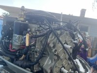
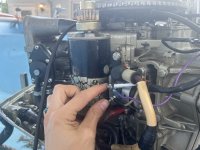
image.jpgimage.jpg


Also here is the boots I manufactured to replace the old cracked ones.. hopefully they work lol.
image.jpg
 
Top