Charging voltage drop with diode isolator

Wave34

Petty Officer 1st Class
Joined
Oct 17, 2017
Messages
336
I find that my batteries could give more when I am 2 days at anchor.

At home, with the 120V charger, I have almost 14V at the batteries.
So they are fully charged when I quit home.
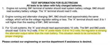
On the water, when the engine is running, there is like 13V at the batteries and 13.7 at the alternator B+ post which is normal because of the diode isolator.
So my batteries will never charge to full capacity.

I read that some alternator have a 'S' terminal that can be wired to the batterie so that becomes the reference charging point for the alternator, and solve the problem having the diode isolator dropping 0.7V to the batteries.

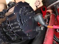
There is a purple wire going out of the alternator.
I don't know its function.
But, if it is a sensing input, it's not going to the batteries.
If it is a sensing input, could I just wire it directly to the batteries to increase the alternator charging voltage.
I would get something like 13.8V at the batteries, and 14.5 at the B+ terminal...
4.jpg
 

JimS123

Fleet Admiral
Joined
Jul 27, 2007
Messages
8,162
Batteries are best charged with a 3-stage Smart Charger. The "juice" is varied according to what the battery needs. There are different settings for wet cell, AGM and gel batteries.

Engine alternators are more "maintainers" than anything else.

If you want to charge on the hook, get a Smart Charger and a genny. Making electrical mods will likely fry the battery. Overcharging at the wrong place will boil it over.
 

alldodge

Moderator
Staff member
Joined
Mar 8, 2009
Messages
42,054
Agree, the isolator is a set of diodes. Each diode has a voltage drop of 0.7V

A fully changed battery should read 13.7V after being removed from charge and having sat for couple hours

Alternator and battery chargers would normally output around 14.5V

Alternator output is controlled by the sense lead which is the purple wire which is part of the engine harness. The ALT output lead normally goes to the starter post, but with an isolator the output would be connected to the the isolator. With the isolator the starter post and the motor would only see around 13.8V (14.5 - 0.7)

Moving the sense lead to the battery will increase the voltage output to get the batteries to see closer to 14.5V, but this also may cause an issue with the ALT. Also, only the bank the sense is connected to, will be the only Bat that will see the 14.5V. The ALT output would go to 15.2V which its not designed to do

Note: I had a 3-bank isolator installed by Formula which charged all banks using an isolator. The ALT output lead was connected to the input of the isolator and no other wires were changed
 

JimS123

Fleet Admiral
Joined
Jul 27, 2007
Messages
8,162
A fully changed battery should read 13.7V after being removed from charge and having sat for couple hours

Alternator and battery chargers would normally output around 14.5V
I believe a fully charged lead acid battery should read 12.6-12.7 volts. An AGM is maybe a couple tenths higher.

A Smart Charger bulk charge on a depleted battery will run as high as 14.2 or so volts, but once its near full it will reduce to the float voltage of about 13.2-13.5 volts.

A car may charge in the high 13's, but if the alternator has a problem and goes much above 14 volts it'll fry the battery.
 

QBhoy

Fleet Admiral
Joined
Mar 10, 2016
Messages
8,342
Usually about a 1v drop across a split charge diode. Quite normal I’d say. Normally the battery will show a volt higher than the diode between them though.
 

Wave34

Petty Officer 1st Class
Joined
Oct 17, 2017
Messages
336
alldodge, my alternator output seems to go to the relay box. Take a look at my other post, I have some pictures.
https://forums.iboats.com/threads/alternator-b-wire-vs-relay-box-volvo-penta.742318/
but it's possible that after a relay it goes to the isolator.

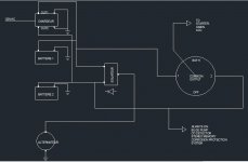
Here is a drawing I made of what 'I think' is my electrical circuit in my boat by tracing as much as I could the wires. I didn't draw the relay box since it seems to be bypassed now. (ref my other post).

circuit batteries.JPG
 

Wave34

Petty Officer 1st Class
Joined
Oct 17, 2017
Messages
336
Batteries are best charged with a 3-stage Smart Charger. The "juice" is varied according to what the battery needs. There are different settings for wet cell, AGM and gel batteries.

Engine alternators are more "maintainers" than anything else.

If you want to charge on the hook, get a Smart Charger and a genny. Making electrical mods will likely fry the battery. Overcharging at the wrong place will boil it over.
Jim, those smart chargers, are they only on 120V? Or they can be installed between the alternator and the batteries, in place of the isolator?

It seems that a ACR is installed on newer boats.
If I replace my diode isolator with a ACR, I will gain 0.7 volts when I'm driving the boat, would that make a difference that worth the trouble and expense to install one?
 

alldodge

Moderator
Staff member
Joined
Mar 8, 2009
Messages
42,054
Need better understanding where the wires go, and the relay box.
I'm starting to think that the boat had some kind of relay which charged both banks once the motor started. This might have been replaced with the isolator

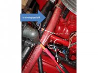
Is the orange wire in pic tapped off and does it go to relay box?
Slide1.JPG

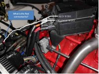
Where does the Red go in this pic?
slide 3.jpg

Your diagram of the isolator is the correct way for it to be installed. Mine was done the same way

If a ACR is used and isolator removed, then the ALT orange wire will go directly to the starter post. The ACR would be installed between the 2-banks
 

ahicks

Captain
Joined
Sep 16, 2013
Messages
3,957
Those diode type isolaters were pretty popular on RV's for a few years, but they were eventually replace entirely with relays of various types. The reason? That voltage drop across a diode. Relays avoid that....
 

alldodge

Moderator
Staff member
Joined
Mar 8, 2009
Messages
42,054
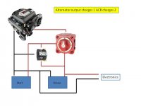
I would tap direct off house bats to feed accessories. This will allow you to leave the single switch always on the start bat unless need both to start motor.

Two Bat one switch and ACR.jpg
 

QBhoy

Fleet Admiral
Joined
Mar 10, 2016
Messages
8,342
Yeah. That’s what I was getting at in my earlier post. It likely was a split charge diode relay.
 

JimS123

Fleet Admiral
Joined
Jul 27, 2007
Messages
8,162
Jim, those smart chargers, are they only on 120V? Or they can be installed between the alternator and the batteries, in place of the isolator?

It seems that a ACR is installed on newer boats.
If I replace my diode isolator with a ACR, I will gain 0.7 volts when I'm driving the boat, would that make a difference that worth the trouble and expense to install one?
The "battery chargers" that I have are all 120 volts. Its the kinda thing you have in your basement so you can charge your boat and tractor batteries in the Winter. "Smart" merely means that it is 3-stage and it varies the voltage according to the state of the battery.

I have seen bass boats and others with dual batteries that have a "charger' permanently mounted in the boat. You merely plug them into a wall plug in the garage after your boat trip. They would be most useful for a trolling motor battery, where the "motor" does not charge the battery.

I'm not electrical saavy, so I don't know about ACRs and changing diodes. But I would be careful about doing that. I certainly would not want to add any voltage to an existing system. Many years ago I had a voltage regulator in my car go bad and the voltage spiked. The car didn't have idiot lights and I neglected to read the gauge. When I came out of the grocery store smoke was coming out from under the hood. The battery boiled over and acid was dissolving the plastic, paint and undercoating. Made for a nasty tar puddle in the parking lot.
 

Wave34

Petty Officer 1st Class
Joined
Oct 17, 2017
Messages
336
Need better understanding where the wires go, and the relay box.
I'm starting to think that the boat had some kind of relay which charged both banks once the motor started. This might have been replaced with the isolator

Is the orange wire in pic tapped off and does it go to relay box?
View attachment 333825

Where does the Red go in this pic?
View attachment 333828

Your diagram of the isolator is the correct way for it to be installed. Mine was done the same way

If a ACR is used and isolator removed, then the ALT orange wire will go directly to the starter post. The ACR would be installed between the 2-banks
Yes the orange is tapped off at your blue arrow, and the other end seems to go to the relay box.
The Red you are pointing to has one end to the ALT output (new wire), but the other end is buried in the wire loom.
 

alldodge

Moderator
Staff member
Joined
Mar 8, 2009
Messages
42,054
Yes the orange is tapped off at your blue arrow, and the other end seems to go to the relay box.
The Red you are pointing to has one end to the ALT output (new wire), but the other end is buried in the wire loom.
Ok, the box was removed and the isolator was put in its place.
 

sam am I

Commander
Joined
Jun 26, 2013
Messages
2,169
@Wave34

"I read that some alternator have a 'S' terminal that can be wired to the batteries so that becomes the reference charging point for the alternator, and solve the problem having the diode isolator dropping 0.7V to the batteries."

Yes

"There is a purple wire going out of the alternator.
I don't know its function.
"

Purple is the alt's "excite" wire, it goes to the ignition and it specifically just "switched 12v"


"But, if it is a sensing input, it's not going to the batteries."

It shouldn't, it's the "excite" wire and it wired correctly to the ignition switch


"If it is a sensing input, could I just wire it directly to the batteries to increase the alternator charging voltage."

Your current Alt is internally wired to "local sense", either need to modify it or get a 3 wire type......

B+ stud goes to isolators battery input stub
#1 terminal/purple(sometimes blk) wire (excite/switched 12V)
#2 terminal/red wire (sense wire)


"I would get something like 13.8V at the batteries, and 14.5 at the B+ terminal..."

With your alt configured in "remote sense" mode and your batteries being fed through a diode isolator....

a) With old school silicone, the diodes Vf is typiclly 0.5V (low current) to perhaps 1V (max current).
b) With Schottky diodes, Vf can be as low as 0.3V (low current) and 0.45V(max current)

So yes, with silicone, batts something like 13.8 to 14.2V and alt's B+ max'd @ 14.8V to 15.2V or with schottky, batts still 13.8V to 14.2V but alt's B+ max'd @ 14.25V to 14.65V


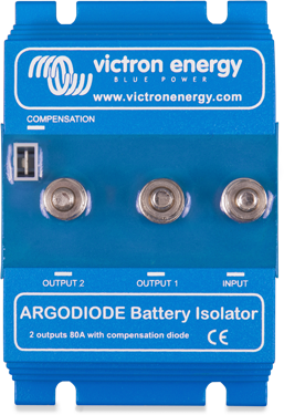
I have one of these, don't currently run it as my boat rec/reg won't excite through it but your alt would, it contains a built in comp diode to overcome sensing one batt.........HOWEVER,you can roll your own though by adding a single diode in series with the remote sense lead and attaching it to the isolator's "batt's input stud"
 
Last edited:

Wave34

Petty Officer 1st Class
Joined
Oct 17, 2017
Messages
336
Ok, the box was removed and the isolator was put in its place.
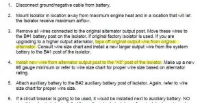
It makes sense. I just found on internet the manual on my diode isolator, and they say to cut the B+ wire and pass another wire to the isolator.
I'm surprised that my boat didn't come already equipped like that from Chaparral...


volt drop1.JPG
 

alldodge

Moderator
Staff member
Joined
Mar 8, 2009
Messages
42,054
I'm surprised that my boat didn't come already equipped like that from Chaparral...

Probably didn't come that way because it had the relay box on top the motor. The box stopped working or didn't work very well, and then the isolator was installed
 

Wave34

Petty Officer 1st Class
Joined
Oct 17, 2017
Messages
336
@Wave34

"I read that some alternator have a 'S' terminal that can be wired to the batteries so that becomes the reference charging point for the alternator, and solve the problem having the diode isolator dropping 0.7V to the batteries."

Yes

"There is a purple wire going out of the alternator.
I don't know its function.
"

Purple is the alt's "excite" wire, it goes to the ignition and it specifically just "switched 12v"


"But, if it is a sensing input, it's not going to the batteries."

It shouldn't, it's the "excite" wire and it wired correctly to the ignition switch


"If it is a sensing input, could I just wire it directly to the batteries to increase the alternator charging voltage."

Your current Alt is internally wired to "local sense", either need to modify it or get a 3 wire type......

B+ stud goes to isolators battery input stub
#1 terminal/purple(sometimes blk) wire (excite/switched 12V)
#2 terminal/red wire (sense wire)


"I would get something like 13.8V at the batteries, and 14.5 at the B+ terminal..."

With your alt configured in "remote sense" mode and your batteries being fed through a diode isolator....

a) With old school silicone, the diodes Vf is typiclly 0.5V (low current) to perhaps 1V (max current).
b) With Schottky diodes, Vf can be as low as 0.3V (low current) and 0.45V(max current)

So yes, with silicone, batts something like 13.8 to 14.2V and alt's B+ max'd @ 14.8V to 15.2V or with schottky, batts still 13.8V to 14.2V but alt's B+ max'd @ 14.25V to 14.65V


I have one of these, don't currently run it as my boat rec/reg won't excite through it but your alt would, it contains a built in comp diode to overcome sensing one batt.........HOWEVER,you can roll your own though by adding a single diode in series with the remote sense lead and attaching it to the isolator's "batt's input stud"

Thanks for the info.
Yes the 'excite' is internal and I won't modify the alternator.
The Argo isolator 'FET' semiconductor seems to be a good solution, with a maximum of 0.1V drop at high current, and less drop at low charging rate.
Either that or the ACR, but both seem to solve my problem.

You say that you cannot install it on your boat because there is no 'excite' output, but I see one small terminal named 'energize' won't that be the trigger signal for your alternator? just taking a guess...

In my diode isolator manual, it says that if the voltage is too low at the battery, the alternator needs to be modified for external sensing. This is the solution they offer.
The problem with a modified alternator is if it breaks, it is not possible to just order a new one, this specific one needs to be repaired with the delays.
 

Attachments

  • volt drop.JPG
    volt drop.JPG
    41.8 KB · Views: 2
Top