Boat rewiring

chamilton68

Recruit
Thread starter
Joined
Jul 6, 2012
Messages
4
Hey folks,

This is my first time to post. I am gearing up to undertake rewiring my 16-foot fiberglass tri-hull. This is an older boat, that I rebuilt the inside of this spring (thanks to the many great posts and videos I found here!) At the time, I replaced enough wiring to keep things working, but knew that I would need to completely overhaul the wiring eventually.

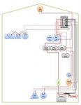
I have created a diagram of all of the electrical components on the boat, which is attached. This is the first wiring diagram I've ever made, so please don't laugh (too hard) at it. I tried to position everything as it is laid out in the boat, and use standard wiring colors for ease of viewing.

What I'm looking for is someone to take a look at the diagram, and let me know if there are ways I could do things more efficiently. I'm planning to add a fuse panel with a bus bar to try to simplify things (currently there are a lot of wires with individual in-line fuses), but it seems like there are still a lot of wires running around with the way I have it laid out.

Any thoughts/suggestions for improvement would be GREATLY appreciated!

Chris
Boat Wiring Diagram.jpg
 

Silvertip

Honorary Supreme Mariner
Joined
Sep 22, 2003
Messages
28,772
Re: Boat rewiring

Your diagram is too small to see details but from what I can see you have the switches and fuses wired wrong. The current path should always be from the battery, through main fuse or breaker (ok in diagram) to the POS buss on the fuse panel (ok) but then you show the switches "before" the fuses leading to the various devices. Fuses need to be installed before the switches. I can't make out what the triangles, circles and squares are so I can't help with that unless you enlarge the diagram. Just so you know, the Nav/Anc switch is needs to be an ON/OFF/ON switch -- not a simple SPST (On/Off) type.
 

chamilton68

Recruit
Thread starter
Joined
Jul 6, 2012
Messages
4
Re: Boat rewiring

Bubba,

I'm rewiring the electrical components on the boat (lights, depth guage, instruments, bilge, etc.), not the motor. The boat is a 1979 fiberglass hull from a manufacturer that's no longer in business, so there aren't any schematics to follow. The wiring that's in now was obviously replaced at some point in the boat's history, and was pretty sloppily done. I've added some fuses to the existing wiring, and replaced some of the bad wires, just to get it up and running, but I want to take it apart and make sure it is all done right.

Silvertip,

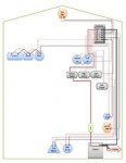
I'm uploading another image file. Hopefully, it will be easier to read. The one I had opens up large on my computer, but was compressed when it uploaded. The only switch I have before the fuses is a master switch (at least that's what I intended). My thinking on that was to have a master switch to shut everything down with. All of the other switches (Bilge, Nav/Anc, and Trim) are after the fuse panel. The triangles, circles and squares are the various components (stereo, depth guage, instruments, lights, etc). As far as the Nav/Anc switch, I'm planning to keep the existing one, since it's in good shape (it's a 3-position pull-out). All of the other switches will be getting replaced.

If the new image is still to small to read, let me know and I can post a link to the image on another server.

Thanks for the help!

Chris

Boat Wiring Diagram.jpg
 

Don S

Honorary Moderator Emeritus
Joined
Aug 31, 2004
Messages
62,321
Re: Boat rewiring

Still too small to see. A link to larger image would be great!
 

chamilton68

Recruit
Thread starter
Joined
Jul 6, 2012
Messages
4
Re: Boat rewiring

Everything you mentioned will be in the engine wiring schematic. Doesn't really matter who made the hull, they follow the wiring schematic from the engine supplier/manufacture and boating industry wiring standards including recommended wire colors. (The engine manufactures scematics always include the dash and usually any accesories.)

Tell us what engine/drive you have and I'll see if I have the schematic handy.

Well, I've learned something new today! It's a 1979 Mercury 90 HP outboard, Inline 6.

I have uploaded the original pdf document of my schematic that I had created to Google docs. The link to view it is here. Google docs lets you zoom the view in, so it should be easy to see now.

Thanks again for the continued help!

Chris
 

Silvertip

Honorary Supreme Mariner
Joined
Sep 22, 2003
Messages
28,772
Re: Boat rewiring

Looks ok. However, the ground connections on the fuse panel should all be shown schematically as connecting to the same point rather than directly across from the each +12 volt side of the panel. As shown, it implies the fuses go across those two points which would create smoke. Electrically it is ok but schematically it raises questions. Likewise the positive buss would be a solid line going down the INPUT (feed) side of the panel. The OUTPUT (load) side of the panel would be where you all the black ground connections. The fuses then bridge the two sides of the panel. Picky to be sure. Just pointing out how diagrams are done.
 
Joined
Feb 17, 2012
Messages
2,906
Re: Boat rewiring

from your diagram you are not using any of the engine wiring harness for power which normally does trim and tilt and acc feed. this is not a problem as long as you remember not to use them. it does mean the tach will be getting power when ever you are using lights etc instead of it only getting power when the engine is running. if you have a metal gas filler cap add a ground for that. trim switch goes to relays not the pump. stereo might require a second power wire from the battery depending if it has a security code. stereo might require its own fuse depending on how big it is. dc plug (cigarrette lighter might require its own fuse depending on what you plan to use on it).
 

chamilton68

Recruit
Thread starter
Joined
Jul 6, 2012
Messages
4
Re: Boat rewiring

Thanks, Silvertip. I wasn't really sure how to diagram that, or what the fuse panel would really look like. I was more just basing it off the idea that I would use a 6-terminal panel.

Glenn, I actually am going to use the wires from the wiring harness for the trim and tach. I just couldn't figure out a good way to indicate that on the diagram, so I just showed them separate. As for the trim switch, it's currently wired to the solenoids, which are mounted on the pump. I just didn't get that detailed. You mentioned that the stereo and cigarette lighter might require their own fuses. Why would they need separate fuses from the fuse panel? Neither of those are switched, so the way I have it diagrammed now, power is running directly from the fuse panel to each of those components.

Another question I had was about the black ground wires. As I have it diagrammed, most of the components have their own separate ground wire connections running back to the bus. Is it possible to combine and share a black ground connections? How about it one component is switched, and another isn't? For example, on the starboard side towards the stern, I have a DC plug, and the anchor light. The anchor light is switched, but the DC plug is not. Could I run a single black wire back to the bus bar for both of them, or do they need separate ones?

Chris
 
Joined
Feb 17, 2012
Messages
2,906
Re: Boat rewiring

fuses are to protect the wire and item from catching fire so if you have a high amp load attached to a low on the same fuse then theres a small risk of a fire. for example the clock has a tiny wire originally as its a very small amp draw but the stereo has a large wire as it need more power. the small wire might overheat when shorted before the fuse thats set for the larger wire blows. the grounds can be bugged together to save wire but thats not a real good idea unless you can remember where all the joints are (rear light and biege pump are normally tied together then taken to the battery or ground buss). i would run all grounds to the buss if possible. if you do bug the grounds together then upsize the wire to the shared load so cig lighter plus light plus etc etc. im advising you on what you should do not what you have to do. once trim and inst are removed from the fuse panel and surported by the engine in line fuse then you will only have 4 fuses and 2 spare on a 6 fuse block
 
Top