Best way to connect 6 awg to 14 awg stranded wire

Sailsea56

Cadet
Joined
Dec 1, 2024
Messages
6
I have a 56 ft saiboat with a 24 volt system with an autopilot computer midships with a power wire going to an electric motor powering a hydraulic pump driving a ram attached to the quadrant in the lazarette, a potentially wet place so needing a good waterproof connector system. The wire feed from the computer is 6 AWG (to avoid voltage drop) and the motor power wire is 14 AWG so I am looking for the best system to connect them securely and keep them dry. I have looked at stepped down butt connectors but the size difference is too great (I think) unless there is something out there I don't know about. How about bolting together two ring connectors then liquid electrical tape then heat shrinking the whole thing? Any ideas? Thanks
 

Lou C

Supreme Mariner
Joined
Nov 10, 2002
Messages
12,716
Even tho it’s said not to solder for marine wiring sometimes it’s tough to properly crimp different gauge wire.
 

dingbat

Supreme Mariner
Joined
Nov 20, 2001
Messages
16,091
Several ways to do this….

Use a 2-14 awg splice/reducer coupler. Top with epoxy lined heat shrink

Get a 6-10 awg butt splice with epoxy lined heat shrink. Double up the 14 awg to fit crimp

Use a 14-8 submersible cable splice kit. Trim off the outer strands of the 6 awg to fit in the coupler
 

cyclops222

Lieutenant
Joined
Mar 21, 2024
Messages
1,343
I just strip off enough insulation so I can FOLD the smaller wire strands several times. To fit a little loosely in the bigger hole. A normal hand compression plier can squeeze it tight.
 

ESGWheel

Chief Petty Officer
Joined
Aug 29, 2015
Messages
473
They make “crimp-solder-seal’ butt connectors which have the solder already inside and when heated up with an air gun it melts the solder and shrinks the outer sleeve. While I did not find any for 6 AWG here is a link for 8 AWG, link.

They also make what is ‘dual walled’ heat shrink tubing. This shrink tubing has an adhesive on the inside wall that glues the whole assembly together and makes it watertight. Here is a link for some. Make sure your get the 3 to 1 shrink ratio.

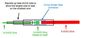
With these in hand, and as suggested above, double, triple, etc. up as needed on the 14 AWG to fit like an 8 AWG into one side. And for the 6 AWG trim off some strands as necessary to fit in the other side. Prior to putting it all together slide on a length of heat shrink onto the 8 AWG wire that is long enough to cover the entire splice plus some. Use the diameter of tube that is one size larger than the wire, so a loose fit. On the other side put some lengths of shrink tubing simply to “build up” that wire’s diameter so that the larger piece will shrink tightly around these smaller pcs (which will also shrink down on the smaller wire). See diagram for a visual on this and note how the smaller ones extend out from the largest ones. If need be, experiment on some scrap wire to get the right combination.

Wire Splice.jpg
 

Sailsea56

Cadet
Joined
Dec 1, 2024
Messages
6
Several ways to do this….

Use a 2-14 awg splice/reducer coupler. Top with epoxy lined heat shrink

Get a 6-10 awg butt splice with epoxy lined heat shrink. Double up the 14 awg to fit crimp

Use a 14-8 submersible cable splice kit. Trim off the outer strands of the 6 awg to fit in the coupler
Thanks. I'll look into these solutions
 

Sailsea56

Cadet
Joined
Dec 1, 2024
Messages
6
They make “crimp-solder-seal’ butt connectors which have the solder already inside and when heated up with an air gun it melts the solder and shrinks the outer sleeve. While I did not find any for 6 AWG here is a link for 8 AWG, link.

They also make what is ‘dual walled’ heat shrink tubing. This shrink tubing has an adhesive on the inside wall that glues the whole assembly together and makes it watertight. Here is a link for some. Make sure your get the 3 to 1 shrink ratio.

With these in hand, and as suggested above, double, triple, etc. up as needed on the 14 AWG to fit like an 8 AWG into one side. And for the 6 AWG trim off some strands as necessary to fit in the other side. Prior to putting it all together slide on a length of heat shrink onto the 8 AWG wire that is long enough to cover the entire splice plus some. Use the diameter of tube that is one size larger than the wire, so a loose fit. On the other side put some lengths of shrink tubing simply to “build up” that wire’s diameter so that the larger piece will shrink tightly around these smaller pcs (which will also shrink down on the smaller wire). See diagram for a visual on this and note how the smaller ones extend out from the largest ones. If need be, experiment on some scrap wire to get the right combination.

View attachment 403938
Many thanks for the detailed response and the illustration. Very clear. So trimming some strands of the wire a bit is acceptable I guess and won't cause voltage drop?
 

Sailsea56

Cadet
Joined
Dec 1, 2024
Messages
6
I just strip off enough insulation so I can FOLD the smaller wire strands several times. To fit a little loosely in the bigger hole. A normal hand compression plier can squeeze it tight.
Thanks. So folding the smaller wire is an accepted solution? Presumably there's a limit to how many times you can fold it, or maybe not?
 

cyclops222

Lieutenant
Joined
Mar 21, 2024
Messages
1,343
No limits.............. Except that there is no fuse or Circuit Breaker to protect the small wire. During a short circuit. During a device, causing a dead short.
 

dingbat

Supreme Mariner
Joined
Nov 20, 2001
Messages
16,091
So trimming some strands of the wire a bit is acceptable I guess and won't cause voltage drop?
The reason you can’t find a connector is that the wires are ridiculously mismatched to be spliced

From an electrical stand point, the 6 awg wire (13.3) has 6 times the carrying capacity as 14 awg. wire (2.08). At this point the 14 awg wire becomes the fuse.

Normally, the 6 awg supply and ground wire would feed a distribution panel. The feeds to the computer and motor would be fused and distributed from there.
 

ESGWheel

Chief Petty Officer
Joined
Aug 29, 2015
Messages
473
So trimming some strands of the wire a bit is acceptable I guess and won't cause voltage drop?
Sailsea56, your question has now morphed and while it is understandable, upon reflection I should have been more curious in exploring the holistic issue you are trying to slove. As others are pointing out this idea of large to small wire is not a generally accepted practice for safety reasons. In my mind you had a permanently connected 6AWG wire coming from “computer” and another permanently connected 14AWG from the “pump” that you needed to spliced together and all other elements of proper fusing and calculations of voltage drop were accounted for.

I am now going to assume that is not the case and would ask that you help us understand the broader picture. For example:
The pump is hard wired with a pig tail of 14AWG wire that is yy feet long. It as a rating of xx Amps. The power source for this pump comes from xxx and has terminal connections where I can install the needed wire. This xxx has a max output rating of zz amps to control this pump. The distance between the power source and the pump is approx. xx feet. The pump control already (or does not) have a fused output for the pump rated at xx.

This is the kind of info that is really needed to help in a proper way. Thanks.
 

briangcc

Commander
Joined
Jul 10, 2012
Messages
2,365
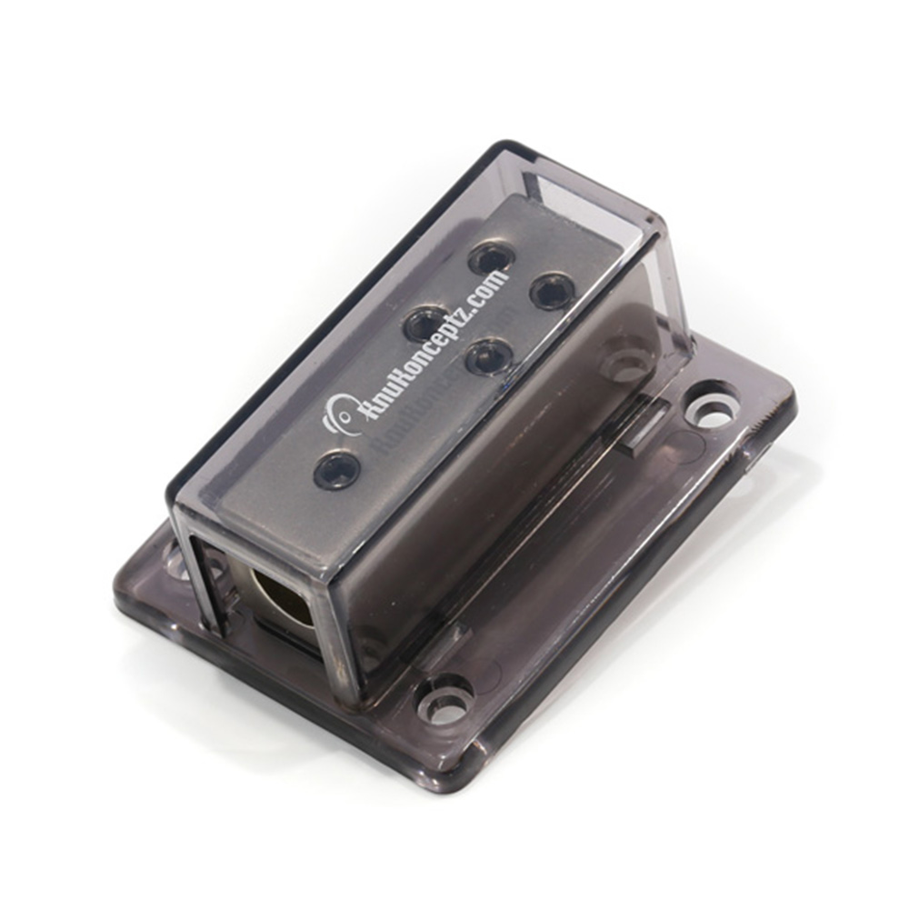
I would look at something like this:


They also sell reducers/adapters.

They're high end stuff in the car audio field. I have a couple battery adapters in my car - had them for years without issue.
 
Top