Another Maine Starchief

laurentide

Lieutenant Commander
Joined
Jul 24, 2011
Messages
1,869
You're making quick work of the demo. My top windshield has interlocking channels...I don't exactly remember how it came apart, but it was self-explanatory once I got into it.

My $0.02 on the fuel tank is as far forward as you can get it. I have the OEM tank under the splashwell with two batteries on the other side. When I put the two deep cycles under the middle berth hatch it rode like a different boat. Much better! And she'll stay on plane at 12 mph now at 3500 RPM on the 70hp. That makes for low fuel costs. You really need some weight mid-forward to offset the outboard weight.
 

GA_Boater

Honorary Moderator Emeritus
Joined
May 24, 2011
Messages
49,038
I don't know if your WS is the same as the one I added to my tinny, but the side window frames slid down into interlocking channels in the front frame.

Plus 1 on moving weight forward. Every pound helps.

Nice boat selfie. :D. Wonder if the PO before your seller did the polishing job? Polishing the hull and the double floor just don't jive!
 

oldhaven

Chief Petty Officer
Joined
Aug 30, 2015
Messages
576
You're making quick work of the demo. My top windshield has interlocking channels...I don't exactly remember how it came apart, but it was self-explanatory once I got into it.

My $0.02 on the fuel tank is as far forward as you can get it. I have the OEM tank under the splashwell with two batteries on the other side. When I put the two deep cycles under the middle berth hatch it rode like a different boat. Much better! And she'll stay on plane at 12 mph now at 3500 RPM on the 70hp. That makes for low fuel costs. You really need some weight mid-forward to offset the outboard weight.

Thanks again, just the advice from experience I need, and forward it is, I may have to do a short bridge deck like Brig did on his to cover the fill and vent up by the cabin bulkhead. The tank is a Moeller FT2899, or it sometimes has a number 032528. I will have to move the stringers about an inch in that area, since the tank is 24.5 wide and my stringers are 24 apart, We'll see when it gets here, but on paper it looks like a good fit.

Ron
 

oldhaven

Chief Petty Officer
Joined
Aug 30, 2015
Messages
576
For CW:

I am planning my transom layout and would like to use the fixed kicker bracket you used, though my 8 Merc is a long shaft. Does its use preclude the installation of Smart Tabs? Have you found them unnecessary? Another thought is it build the transom profile higher in that area so no bracket is necessary. that would involve modifying or fabricating a new transom cap, but it is a thought.

Ron
 

laurentide

Lieutenant Commander
Joined
Jul 24, 2011
Messages
1,869
Ron, the bracket I used does in fact rule out smart tabs. But if you want to use a kicker I highly recommend the fixed bracket with a long shaft. It's much, much sturdier than the adjustable brackets, and the 20" kicker is still out of the water at rest and on plane when raised. If you do the forward mount fuel tank you won't miss the tabs that much, and you won't have to worry as much about bow steer in a following sea.
 

oldhaven

Chief Petty Officer
Joined
Aug 30, 2015
Messages
576
Thanks CW. I have some half inch holes from the previous plywood bracket that I have to fill anyway, and I can probably use them to mount the fixed aluminum one. I will be putting batteries mid ships and will likely use the under splashwell area for light storage. Nice to hear about that low planing speed.
 

Watermann

Starmada Splash of the Year 2014
Joined
Jan 12, 2013
Messages
13,787
The tank is a Moeller FT2899, or it sometimes has a number 032528. I will have to move the stringers about an inch in that area, since the tank is 24.5 wide and my stringers are 24 apart, We'll see when it gets here, but on paper it looks like a good fit.

Ron

Not sure if I googled up the right fuel tank Moeller FT2899 looks like the tank I got out of my donor boat only a little different size. You'll also have to account for the neoprene to cushion the tank as it rests on top the ribs. Yours even has the similar indentations for the tank hold down brackets which should also have the neoprene under them against the tank. It's really nice having the under deck belly tank mid-ship but it take just a few very doable modifications.

One mod was adding firing strips to the tops of the ribs to raise the sides level with the AL deck supports. In the pic below you can see the neoprene strips that are cushioning the tank on top of the ribs and firing strips. I was at a loss on how to secure the neoprene to the ribs, thought about blind rivets but ended up using 5200 to adhere them, weighted the tank for a few days and they were stuck tight.

I really enjoy your forward progress, it brings back some great memories for me working on my Chief. Looking forward to seeing your Chief come back together!

IMAG1446.jpg
 

oldhaven

Chief Petty Officer
Joined
Aug 30, 2015
Messages
576
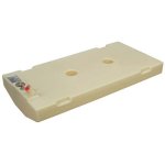
Thanks for the encouragement! My tank does not have the nice low filler, but I can work around that. Here is a stock picture and I will try one of it in the boat when I get back in town and near a better keyboard.

Ron
 

Attachments

  • image.jpg
    image.jpg
    16.3 KB · Views: 1

oldhaven

Chief Petty Officer
Joined
Aug 30, 2015
Messages
576
Here are my tank options with the 27 gallon tank. Both require moving stringers outboard about an inch each and raising the floor slightly as Watermann did.


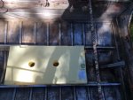
Filler just inside the standard position of the splash well doors. Weight distribution will be better than above deck tanks under the splash well, and the filler can protrude above the deck and is easily accessible. There is an existing filler cap and vent built into this side of the splash well top rail, so I don't have to fill them in and punch a new hole in the gunwale up by the cabin. Leaves room for a full length door to cabin. I will be putting two big batteries forward so this may be OK for weight distribution, since the fuel weight will be variable depending on state of fill. The tank is 49" long, so it extends pretty far forward from the stern. IMG_0226 (1024x765).jpg


Forward against the bulkhead. Requires a boxing in of the filler and a shorter door. I have a short set of antique wooden cabin doors from a log driving boat that I could use.
IMG_0234.JPG

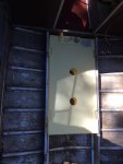
here you can see the stringers are just about right, but not quite.
IMG_0233.JPG


I will have some time to think about this over the winter, but I now know I have to remove the stringers to move them out a bit, so that will help with clean out. Good idea about the neoprene bedding and gluing it down. I will have to build a tank chamber bulkhead between the stringers and will pad it all around.

Ron
 
Last edited:

Watermann

Starmada Splash of the Year 2014
Joined
Jan 12, 2013
Messages
13,787
That set up is about as good as you're going to get alright with all the plumbing coming out under the slpashwell. :thumb:
 

oldhaven

Chief Petty Officer
Joined
Aug 30, 2015
Messages
576
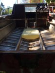
Today I have the stringers out and all of the wood out of the cabin. I took advantage of this mornings deluge to put in the plug and do a preliminary broom up of the aluminum hull interior. the hull got about a foot of water at the transom, and I took the plug back out , fearing for the weight doing something bad.

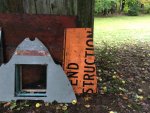
Here is a picture of the bottom of the cabin sole after I removed it. Pretty obvious where that came from. It might have said END (DE)CONSTRUCTION
IMG_0263.JPG
 

oldhaven

Chief Petty Officer
Joined
Aug 30, 2015
Messages
576
Transom Out

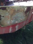
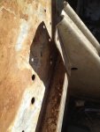
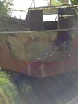
I pulled the transom today, and also removed the outer transom plywood piece that was under the motor. I had feared finding bad things there, but the rest of the boat is so corrosion free so far that I had hoped for the best. Alas, not to be. There is quite a bit of corrosion right at the knee brace area, including a silver dollar sized hole. The corrosion stops right at the bracket or ledge for the transom, and all is good beyond 6 inches in any direction of the hole, but it is apparent that some corrosive fluid developed there and sat for a while. the transom plywood was wet all along the ledge. I can only take heart that I have seen other successful repairs of this type thing here on the forum, and I will do some review of methods in the next few days. I can see I will be adding a plate on at least one side of this area. This makes me wonder if having drain holes in that ledge might be a good thing to add.

Ron
IMG_0564.JPG
IMG_0565.JPG
IMG_0566.JPG
 
Last edited:

64osby

Admiral
Joined
Jul 28, 2009
Messages
6,819
Recently had a discussion about motor pads here. One member here suggested a 1/4" plate of aluminum for a very small tinner. I disagreed with that on that particular boat.

On this boat I think it would be an awesome idea. Cover the whole area with an oversized plate. Solves 2 issues at once. My $.02.
 

GA_Boater

Honorary Moderator Emeritus
Joined
May 24, 2011
Messages
49,038
I agree with 64 on this one. A thick 1/4", oversized motor pad can only help in this case. Wide and deep into good tin.
 

g0nef1sshn

Lieutenant
Joined
Feb 24, 2015
Messages
1,291
Are you gonna take out the knee brace and transom z brace that supports the wood? I did to be able to get mine cleaned up good and I am glad I did. Ofcourse i had to invest in the equipment to learn how to do solid rivets. After a few practice shots they werent too hard to do.
 

dozerII

Admiral
Joined
Oct 25, 2009
Messages
6,527
I agree with the others remove your transom Z brace as well as the knee brace, clean every thing up well and neutrelize. Then put a 1'4 inch aluminum pad on the outside sealed with 5200 and solid rivets and two problems are taken care of.
 

classiccat

"Captain" + Starmada Splash Of The Year 2020
Joined
Dec 20, 2010
Messages
3,412
If that's your only corrosion issue, then you lucked out! :thumb:

+1 on what the other star-dudes recommend.

The only thing that I would recommend is also filling that gaping hole first with JB weld...using a flashing backer and sanding it smooth. Painters tape works great to keep it in place...and from running down the transom skin.

To lessen the amount of JB weld needed, you can rough-cut some aluminum to fill most of the hole.
 

oldhaven

Chief Petty Officer
Joined
Aug 30, 2015
Messages
576
Well, someone else with insomnia besides me. Thanks all. I was hoping to avoid having to do solid riveting and the expense of a solid rivet gun, as I already have to buy a pneumatic pop riveter, but I have seen some good deals on Ebay for used ones, so that's on the list. I have to agree with the all of your advice about the knee brace and the 1/4 plate. To do a permanent repair that gets into good metal, the rivets for the z-brace and at least some of the knee brace will have to be redone. I could probably clean the area behind the knee brace without removing it and getting into the rivets on the bottom of the hull, but there is some suspicious external patching with epoxy or something done down there so it would be wise to look at it when I get to examining the bottom paint. That area looks solid from the inside, unlike the transom. The transom pad on the outside was pretty far gone, so it is hard to tell if it was original from new, but it may be PT ply and an add on, so that might be what happened, and why the rest of the boat looks OK (so far), and this was so bad.

I see that MichaelP added a large plate to his transom and his repair looks great. I will do something similar. The plate will also help stiffen the motor mount area and help deal with the extra holes in the transom aluminum.

A word of caution for others, When removing the plywood transom, (used a high lift to start it) be careful not to get your fingers under the wood if it is above the metal transom skin. I did and it dropped back down a bit and removed some skin from a finger tip. Another 1/2 inch of grip and I would not be typing right now. Those waterlogged things are heavy and make a good guillotine. I did not need a hoist to take it out, but in retrospect, it would have been safer.
 

g0nef1sshn

Lieutenant
Joined
Feb 24, 2015
Messages
1,291
The pnuematic hammer for the solid rivets was 13$ at harbor freight. I had to get everything though. So on a sale day I think I spent just over 200$ for all this. The compressor being the biggest chunk.

The heads I got off a website 25-30$?? I think. But some guys on here just made there own heads out of old chisels that worked fine.

And I sleep fine most nights. It was the 19 month old up at 0400 that ordered me out of bed this early on a off day:eek:


20150406_142328_resized.jpg 20150406_100855_resized.jpg
 

classiccat

"Captain" + Starmada Splash Of The Year 2020
Joined
Dec 20, 2010
Messages
3,412
The transom pad on the outside was pretty far gone, so it is hard to tell if it was original from new, but it may be PT ply and an add on, so that might be what happened, and why the rest of the boat looks OK (so far), and this was so bad.

^^^ that would explain alot!

If you can score a good price on a rivet hammer...they're nice because of their variable speed trigger.

I have that same compressor that gone shows...pretty sweet deal too. If it's a small # of rivets, you can actually get away with a small compressor...i have a 2-gal that I use for trim nailing...and I've used it in a pinch when I only had 10 or so rivets and didn't feel like firing-up the 21gal.

the smaller cost of a small compressor (and oiler, tubing, etc.) might offset the cost of a rivet hammer/proper rivet sets, etc if budget is an issue. (but if you have a pneumatic pop riveter...guessing you already have a compressor...so there goes that fat in your budget :lol: )
 
Top