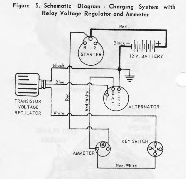
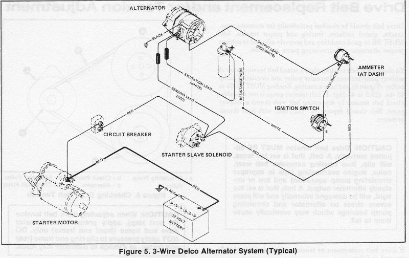
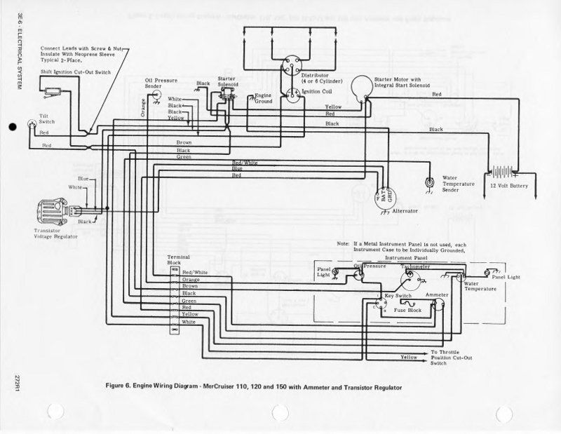
As posted in a previous thread I fried my externally regulated alternator on my '68 Mercruiser 120. I had some wires with worn insulation in the alternator circuit that shorted when I hooked up the battery. I'm taking this unfortunate opportunity to upgrade to an internally regulated alternator. I have studied the wiring diagrams of the current setup as well as the diagrams for the later one wire and three wire setups.
In the future I would like to use the boat for trolling more at low speeds. My concern is that the one-wire alternator, from what I've read, doesn't charge below 1000 or 1500 rpm depending on the source. Would I be better to install the three wire alternator?
The wiring changes appear to be simple enough. The white lead (excitation) goes to the positive terminal on the coil, the red lead (sensing) goes to the positive lead on the starter slave solenoid, and the output lead goes to the positive side on the ammeter. I have an ammeter on the dash that I'll need to upgrade because it's a 50 amp scale. I believe I'll need to upgrade the guage of the wiring to and from the ammeter if I go from the current alternator which I believe is a 42 amp to the 63 amp unit.
I also will need to add a circuit breaker between the starter solenoid and slave solenoid according to the wiring diagram in the 1974 Mercruiser manual. Since I doubt the alternator will ever be outputting the full 63 amps would a 60 amp breaker be appropriate or should it be lower that that?
Thoughts? Thanks in advance for your input.
I did a bad crop of the image for the external regulated alternator. It says at the top it is relay regulated. The diagram is the transistor regulator circuit which is what I have. On the page the description for the diagram was to the left below a lot of text not needed for this discussion.


Last edited:


