Add a Livewell Switch Again

IlliniDoc

Seaman
Joined
Jun 2, 2020
Messages
57
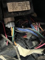
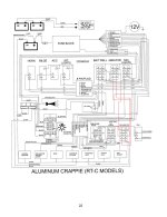
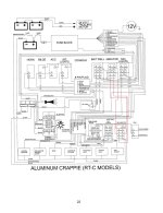
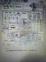
Well a couple years ago I wanted to add a livewell switch to the front of my posted on this forum after a few tribulations Sam am I got me on the right track and I got it done. Well I bought a different boat and would like to do the same thing so you would think just follow Sams original instructions dummy right. Well here is my dilemma,the new boat is a 2016 Ranger RT178c with 2 live wells a separate pump for each well and a single timer runs both pumps, the old boat had a single pump and timer so in my mind the wiring would be a little more complex on the new boat. Would like to know if and how I can add an extra switch to the new boat.
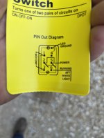
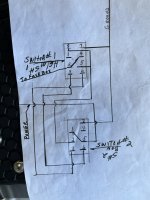
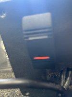
Hopefully the pics are self explanatory.
Thanks in advance for your help.FA885B71-6F18-4913-BBF7-42D2804DA39B.jpeg092D3D1B-5A3A-4535-B1F5-2F2311B5E56C.jpeg
 

IlliniDoc

Seaman
Joined
Jun 2, 2020
Messages
57
I neglected to mention I am only interested in adding another switch to the front livewell. Thanks again for any help.
 

sam am I

Commander
Joined
Jun 26, 2013
Messages
2,169
Are you able to run a few wires forward from the helm to the bow panel?
 

IlliniDoc

Seaman
Joined
Jun 2, 2020
Messages
57
Good to hear from you again Sam.
I believe I can get wires to the front relatively easily.
 

sam am I

Commander
Joined
Jun 26, 2013
Messages
2,169
Thank you, you as well.............So, to keep things as simple as possible and not have you chasing too many odd ball connections and limit bilge diving..........There are probably a few other ways, but I'd add the new bow switch more of less in parallel with the helms switch as follows..........

You'll pick up two (of 5) connections from the bow area as there appears to be a small ground and fused power buss somewhere in the bow you can use.

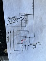
From that bow buss, a ground will go to pin 7 of your new bow panel switch(use same type switch, 8 pin DPDT lighted) and a fused 12V will go to pins 2 & 4 of the new bow switch.

You'll need to run three wires from the helm switch to the new bow switch, grab the connections right off the helm switch that runs the front pump.....So, 3 to 3, 6 to 6, 5 & 8 to 5 & 8.

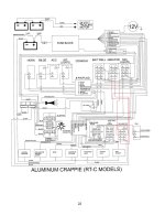
For above, see added red wires and the additional switch("2nd Aerator") added in the "Bow Panel" in the schematic below.

Features are ...........When "on" in either mode(auto or man), either switch's selected settings will light the other switch's "on" indicator light(e.g. if helm switch is left on, the bow's switch[even if in the off position] will have its light lit up and vise versa) .............If either switch is in auto, the other switch will over ride it when switched into its "manual" position.(but not the opposite, manual will trump[Sucks!!] auto)

Ranger Aluminum Front Live Well Switch.jpg
 
Last edited:

IlliniDoc

Seaman
Joined
Jun 2, 2020
Messages
57
Thank you, you as well.............So, to keep things as simple as possible and not have you chasing too many odd ball connections and limit bilge diving..........There are probably a few other ways, but I'd add the new bow switch more of less in parallel with the helms switch as follows..........

You'll pick up two (of 5) connections from the bow area as there appears to be a small ground and fused power buss somewhere in the bow you can use.

From that bow buss, a ground will go to pin 7 of your new bow panel switch(use same type switch, 8 pin DPDT lighted) and a fused 12V will go to pins 2 & 4 of the new bow switch.

You'll need to run three wires from the helm switch to the new bow switch, grab the connections right off the helm switch that runs the front pump.....So, 3 to 3, 6 to 6, 5 & 8 to 5 & 8.

For above, see added red wires and the additional switch("2nd Aerator") added in the "Bow Panel" in the schematic below.

Features are ...........When "on" in either mode(auto or man), either switch's selected settings will light the other switch's "on" indicator light(e.g. if helm switch is left on, the bow's switch[even if in the off position] will have its light lit up and vise versa) .............If either switch is in auto, the other switch will over ride it when switched into its "manual" position.(but not the opposite, manual will trump[Sucks!!] auto)

View attachment 362046
Well sir I am in your debt again. It will be a while before I can get back to this project as I have been volunteered for another but I will let you know how it goes.
Again thanks for sharing your knowledge with me.
doc
 

IlliniDoc

Seaman
Joined
Jun 2, 2020
Messages
57
Thank you, you as well.............So, to keep things as simple as possible and not have you chasing too many odd ball connections and limit bilge diving..........There are probably a few other ways, but I'd add the new bow switch more of less in parallel with the helms switch as follows..........

You'll pick up two (of 5) connections from the bow area as there appears to be a small ground and fused power buss somewhere in the bow you can use.

From that bow buss, a ground will go to pin 7 of your new bow panel switch(use same type switch, 8 pin DPDT lighted) and a fused 12V will go to pins 2 & 4 of the new bow switch.

You'll need to run three wires from the helm switch to the new bow switch, grab the connections right off the helm switch that runs the front pump.....So, 3 to 3, 6 to 6, 5 & 8 to 5 & 8.

For above, see added red wires and the additional switch("2nd Aerator") added in the "Bow Panel" in the schematic below.

Features are ...........When "on" in either mode(auto or man), either switch's selected settings will light the other switch's "on" indicator light(e.g. if helm switch is left on, the bow's switch[even if in the off position] will have its light lit up and vise versa) .............If either switch is in auto, the other switch will over ride it when switched into its "manual" position.(but not the opposite, manual will trump[Sucks!!] auto)

View attachment 362046
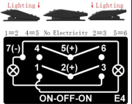
Sam after your reply I was looking for parts to have when I get to this job, can this be done with a 7pin switch? I see you are only using 7 of the 8 pins in your drawing and I can only seem to find 7 pin DPDT lighted switches.
Thanks Doc
 

sam am I

Commander
Joined
Jun 26, 2013
Messages
2,169
Well sir I am in your debt again. It will be a while before I can get back to this project as I have been volunteered for another but I will let you know how it goes.
No worries and yes, let us know please.
Again thanks for sharing your knowledge with me.
doc
You're very welcome
Can this be done with a 7pin switch?
Thanks Doc
Yup, but you'll have to mirror (see revised schematic below) the switch's pinning. This keeps the switch's light functioning as intended (solid on in manual AND cycles w timer in auto).

This assumes that the 7 pin DPDT switch's light (low/gnd side[cathode] if LED) is wired to pin 7 and it's (high/12V side[anode] if LED) are both hard wired to pins 1 and 3.......This is more or less most manu's standard/default config and should work fine.(See second attachment)
 

Attachments

  • Ranger Aluminum Front Live Well Switch_a.jpg
    Ranger Aluminum Front Live Well Switch_a.jpg
    831.9 KB · Views: 19
  • Screenshot 2022-06-05 at 11-56-25 Amazon.com LED Marine Boat 7 Pins Dpdt On-Off-on Rocker Swit...png
    Screenshot 2022-06-05 at 11-56-25 Amazon.com LED Marine Boat 7 Pins Dpdt On-Off-on Rocker Swit...png
    122.9 KB · Views: 23
Last edited:

IlliniDoc

Seaman
Joined
Jun 2, 2020
Messages
57
No worries and yes, let us know please.

You're very welcome

Yup, but you'll have to mirror (see revised schematic below) the switch's pinning. This keeps the switch's light functioning as intended (solid on in manual AND cycles w timer in auto).

This assumes that the 7 pin DPDT switch's light (low/gnd side[cathode] if LED) is wired to pin 7 and it's (high/12V side[anode] if LED) are both hard wired to pins 1 and 3.......This is more or less most manu's standard/default config and should work fine.(See second attachment)
Thanks again Sam sorry to take up your Sunday.
Will follow up with results.
Doc
 

IlliniDoc

Seaman
Joined
Jun 2, 2020
Messages
57
No prob, I wasn't doing squat.......
Sam I have got the wires run and just got the switch. I am taking a pic of the switch pins. They are positioned different than what your schematic shows. Do I mirror your drawing schematic or follow the pin numbers as you have them?
Thanks DocA2C26FD7-4009-41BD-B2F9-DAC3151378DC.jpeg
 

sam am I

Commander
Joined
Jun 26, 2013
Messages
2,169
I assume the new switch's pins 2 and 5 aren't hard wired together as shown in the manu's picture?

Else yes, just follow the pin numbers as depicted/marked on the new switch and hook the wires up as shown in schematic in post #8
 

sam am I

Commander
Joined
Jun 26, 2013
Messages
2,169
No, 2 & 5 of the new switch can't be wired together either internal or external...The switch has to be wired as shown in the schematic post #8

Local two (2) wires at new switches added bow location are...

  1. New switch's pin 5 wired to new switch's pin 1(a jumper if you will), both then wired to +12V in bow buss
  2. New switch's pin 7 wired to ground in bow buss

3 wires you ran are..............

  1. New switch's pin 2 wired to front pump switch's pins 5 & 8(another, but already existing jumper)
  2. New switch's pin 6 wired to front pump switch's pin 3
  3. New switch's pin 3 wired to front pump switch's pins 6
 
Last edited:

IlliniDoc

Seaman
Joined
Jun 2, 2020
Messages
57
View attachment 362557
Probably not how you want to start your day but I think you have finally got through my ignorance. Hooked up front switch as you drew it pump comes on in both positions ( without water couldn’t test timer) confident it will work. My only other issue is the bottom light on new switch is on no matter which position the switch is in. Scratching head, bad switch I have a wire crossed any ideas?69209C8E-B237-4390-A21E-B429BC67143C.jpeg
View attachment 362557
 

Attachments

  • 23A4871B-3C19-4598-8106-50D6B0374AA8.jpeg
    23A4871B-3C19-4598-8106-50D6B0374AA8.jpeg
    1.4 MB · Views: 5

sam am I

Commander
Joined
Jun 26, 2013
Messages
2,169
Lol......It's all good.

I lead you astray, we have to go back in Doc!!

  1. Remove from switch #2 the jumper pins 1 to 5.
  2. Add to switch #2 a jumper from pins 1 to 2 to 4.(See attachments)

Functionality of switch lights are as follows.

With bow switch off position....

  1. Helm switch in manual, helm switch light will be on solid and bow switch top light on solid.
  2. Helm switch on auto, helm switch light will cycle w pump and bow switch top light will cycle with pump.

With helm switch in off position...

  1. Bow switch in manual position, bow switch top light on solid and helm switch light on solid.
  2. Bow switch in auto position, bow switch top AND bottom lights cycles with pump and helm switch light cycles with pump.

BONUS..............Switches off, lights off!!! ;)
 

Attachments

  • 69209C8E-B237-4390-A21E-B429BC67143Ca.jpg
    69209C8E-B237-4390-A21E-B429BC67143Ca.jpg
    3.2 MB · Views: 10
  • Ranger Aluminum Front Live Well Switch_b.jpg
    Ranger Aluminum Front Live Well Switch_b.jpg
    832.1 KB · Views: 11
Last edited:

IlliniDoc

Seaman
Joined
Jun 2, 2020
Messages
57
Well sir with some head scratching and some expertise on your part we have completed another successful install. As I said haven’t put water to it to test the timer but confident it will work
Thanks for all your help and patience. Not sure I will have enough beer to repay.
God Bless and have a great rest of your day.
 

sam am I

Commander
Joined
Jun 26, 2013
Messages
2,169
Well sir with some head scratching and some expertise on your part we have completed another successful install. As I said haven’t put water to it to test the timer but confident it will work
Thanks for all your help and patience. Not sure I will have enough beer to repay.
God Bless and have a great rest of your day.
You're quite welcome, couldn't have done it w/o you doing the dirty work ;) The additional switch up front is an awesome idea BTW!

You owe me nothing sir and your thank you is the best re-payment in the world these days.
 
Last edited:

IlliniDoc

Seaman
Joined
Jun 2, 2020
Messages
57
sam am I just wanted to follow up with you regarding the project. Put water to it today no surprise everything works as it should, couldn't have done it without your help.
Thanks again
 
Top