Add a live well switch

IlliniDoc

Seaman
Joined
Jun 2, 2020
Messages
57
Getting older, fatter and lazier I would like to add a live well switch to the front of my boat. The boat is a 2001 Lowe 170 bass boat. The boat has 2 live wells and both are operated with 1 switch on the console it has an manual and an auto mode with a timer. Is it possible to add a switch to the front and still keep the switch on the console? If it is possible I will have some further questions.

Thanks in advance for any help or advice.
 

sam am I

Commander
Joined
Jun 26, 2013
Messages
2,169
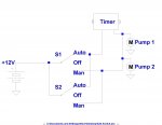
So assuming you still want this extra up front switch to run both wells, like the console does, AND that both the timer and the manual feed signals are +12V (usually are), then just parallel another SPDT(single pole, double throw) switch that of course has +12V on its pole connection and just hook both throw connections to the same places that the current switch has its throws...This maybe easiest at the console switch's throw connections or perhaps spliced down stream somewhere's.

Either switch will work the same and as before as long as the other is left off, however if one is left in auto, the other switch can override it with manual and manual being a moot point.

Truth Table Time

S1 S2 Z
-------------
A + A = A
A + M = M
M + A = M
M + M = M


So reading the first iteration.....If S1 is in auto(A) and S2 is in auto(A), then the result with be the pumps (Z) will run in auto...........
 
Last edited:

IlliniDoc

Seaman
Joined
Jun 2, 2020
Messages
57
Thanks Sam that is what I thought as well. But when I tested for the proper posts and made the connections I keep blowing the fuse. I will try again to find the proper posts to jump to the front if I am unsuccessful I will post a picture of the back of both switches and employ your help again.

Thanks again
Doc
 

sam am I

Commander
Joined
Jun 26, 2013
Messages
2,169
You're welcome Doc,

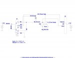
And just for brevity, I've included a draw'ring....

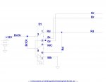
Click image for larger version  Name:	Add Switch.jpg Views:	1 Size:	94.0 KB ID:	10875900
S2 is really no different then a person manually touching a +12V "hot" wire to either S1's throw connections....Should NOT be any fuse blowing issues!
 

IlliniDoc

Seaman
Joined
Jun 2, 2020
Messages
57
The reason I am having difficulty determining the proper posts or pins to connect to and probably why I am blowing fuses is the switch on the console is a 7 pin switch and I am going to a SPDT 4 pin switch (has separate ground for the light) and working under the dash a little cramped, when I get back to it I will remove the switch and jumper to it so I can see what I am doing. I am a little under the weather today so I will not be working on it today. Will let you know when I get back to it. I know it shouldn't make any difference but I have a single pump for both livewells.

Thanks again for your help
 

sam am I

Commander
Joined
Jun 26, 2013
Messages
2,169
the console is a 7 pin switch

Hold up...........Even a illuminated SPDT shouldn't have that many contacts!! So the monster grows, can you get a pic of the back of the switch?

Guessing illuminated DPDT with possibly a bit more wiring than first assumed.

And this might not matter but, what is the action of the switch? 3 Position ON-Off-ON?


it shouldn't make any difference but I have a single pump for both livewells

Correct
 
Last edited:

gm280

Supreme Mariner
Joined
Jun 26, 2011
Messages
14,604
Some times the simplest ideas run afoul.

I agree with sam am I. If this is simply an on/off/timer setup, then paralleling the two switches would be how you should wire the new switch up. But blowing fuses points to something else going on...
 

IlliniDoc

Seaman
Joined
Jun 2, 2020
Messages
57
As I said earlier I am a bit under the weather today don’t much feel like crawling under the dash. Will try to get pics tomorrow. 7 pins were the trigger, I needed to specify that in my original post but as I am sure you have figured out that I know enough wiring to do the work just need to understand how it all works. The console switch has 7 pins but only 6 are used I will post some pics soon. The switch is 3 position MANUAL-OFF-AUTO which is on a timer.


Thanks
 
Last edited:

gm280

Supreme Mariner
Joined
Jun 26, 2011
Messages
14,604
The the previous wiring diagram that sam am I posted should be your guide for the second switch. However, you surely need to verify where ever wire comes from and goes to before doing anything. May surprise you to find out what else is connected there...
 

IlliniDoc

Seaman
Joined
Jun 2, 2020
Messages
57
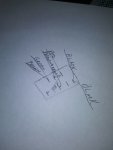
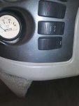
I am having trouble with the pic download so I hope you can make out the wiring. The bottom switch is for acc. the next switch is the livewell switch. My drawing is crude but you can see where the wires go. Hope this helps.

Doc
 

Attachments

  • photo331750.jpg
    photo331750.jpg
    20.3 KB · Views: 5
  • photo331751.jpg
    photo331751.jpg
    111.3 KB · Views: 5
  • photo331752.jpg
    photo331752.jpg
    211.3 KB · Views: 5

sam am I

Commander
Joined
Jun 26, 2013
Messages
2,169
Click image for larger version  Name:	image_331750b.jpg Views:	1 Size:	193.6 KB ID:	10877138

Hmmmm, a few assumptions here, the red is the +12V feed and I got the right switch. and my switch wiring scratching sync's.......doh!!.

Not quite sure what's going on down stream..........oh well, It's late and I didn't get a nap, tomorrow.

Does that light on the switch cycle on and off when the pump is switched to auto? And on solid in manual? Such odd wiring...

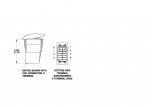
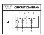
BTW, I blended/photo edited B/2 and J........I hope Carling doesn't mind
 

Attachments

  • V-Series-II-III_datasheet(1)_Page_2a.JPG
    V-Series-II-III_datasheet(1)_Page_2a.JPG
    68.2 KB · Views: 1
  • Add Switch.jpg
    Add Switch.jpg
    97 KB · Views: 1
  • image_331750b.jpg
    image_331750b.jpg
    193.6 KB · Views: 1
Last edited:

IlliniDoc

Seaman
Joined
Jun 2, 2020
Messages
57
I hate to contradict someone who has a ton more knowledge but I am pretty confident that the brown&orange is the 12v feed. That is what is going to my fuse block. Not sure about the light but I will find out in a little while.
If I was up until midnight I would be unable to function til noon.Ha
 

sam am I

Commander
Joined
Jun 26, 2013
Messages
2,169
No worries, I haven't a clue about what's under that dash......I'm flying by a proxy wire here and winging it at this point. This change I think makes more sense...........Still not clear to me why the fuses blew!

Yes, the light on the switch might help us know something, not sure yet

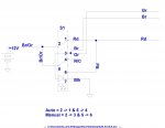
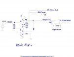
Click image for larger version  Name:	Add Switch.jpg Views:	1 Size:	85.1 KB ID:	10877214
 
Last edited:

IlliniDoc

Seaman
Joined
Jun 2, 2020
Messages
57
I meant the light cycles with the pump. I am putting the boat in the shed may be able to trace some wires.
 

sam am I

Commander
Joined
Jun 26, 2013
Messages
2,169
Sam
Light cycles with the switch.

On solid is either position?

Hmmmm, as drawn (newest, Br/Or for +12V feed) and IF I have the right switch(99% sure), I'm not sure how then the light is coming on when the switch has its contacts lined up from 2 >1 and 5 > 4, unless the light is power by feedback via Br/Gr wires.

If that was the case, I was leaning towards the light would cycle as the timer turned on and off the pump.
 

sam am I

Commander
Joined
Jun 26, 2013
Messages
2,169
I meant the light cycles with the pump. I am putting the boat in the shed may be able to trace some wires.

Ah ha!!! This means something!!! Not sure what though ;)

But I think we're on the right/near path with our documentation thus far, that helps.


Click image for larger version  Name:	Add Switch.jpg Views:	1 Size:	100.7 KB ID:	10877278
 
Last edited:

IlliniDoc

Seaman
Joined
Jun 2, 2020
Messages
57
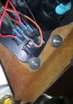
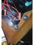
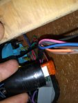
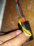
Well Sam I have spent most of the afternoon scratching my head there has to be more to this than I anticipated. I got out my meter today crawled under the dash and traced a few wires some go beyond the console area and I am not sure where they go must go to the pump. The photos I took are assumed to be the timer for the pump. That being said I pulled out the switch so I could check current flow The BLACK wire I assumed to be ground so I used it as ground for the meter checked all the posts first with the switch off only power was at the brown and orange connectors as expected, switched to manual all posts shows 12.4volts (scratch head) so I moved the switch to auto checked posts all posts shows 12,4volts (really scratch head). So just for grits I change to ohms and check the ground for continuity with the hull, shows 7.09 ohms with switch in off position and 7.40ohms with switch in either on position I am not sure what that means but I do know that it should read 0.00 if there is continuity. Needless to say I have nearly reached the conclusion that I do not need that switch in the front, as after today it has (my opinion) far surpassed my electrical prowess. Unless you understand what is going on here and can offer me some light I am ready to table this endeavor for now. I may try to contact LOWE and see if somebody there can shed some light on this situation and how that switch is wired and if I can add a switch. If all that I have said makes sense to you let me know.
Neglected to mention that I grounded to the hull and checked for power had 12.4volts at all posts except where the black wire was attached (separate ground?) I am baffeled.

Thanks for all your help
Doc
 

Attachments

  • photo331839.jpg
    photo331839.jpg
    154.2 KB · Views: 0
  • photo331840.jpg
    photo331840.jpg
    209.2 KB · Views: 0
Last edited:

sam am I

Commander
Joined
Jun 26, 2013
Messages
2,169
So just for grits I change to ohms and check the ground for continuity with the hull, shows 7.09 ohms with switch in off position and 7.40ohms with switch in either on position I am not sure what that means but I do know that it should read 0.00 if there is continuity.

Tiny bits-o leakage curent in ohms setting will show/add some BS resistance to the readings.....This is very normal, ignore plz.

I may try to contact LOWE and see if somebody there can shed some light on this situation and how that switch is wired and if I can add a switch.

Don't bail on me now man!!

If all that I have said makes sense to you

If I said yes, would you believe me?


(separate ground?)

No, and see your above readings to the hull..... This is just that bonding ties the batt neg to the hull (via motor mounting etc and/or directly via bonding wire) but NEVER use hull as a power ground........It is just tied to ground, not a ground.


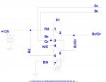
So, a bit late getting back as I was lost in Montana but I got found, Dang it!!...........Anyway, that is a Rig Rite 520 (420 in Washington ;)) timer and it is wired in yer boat as such:

Click image for larger version  Name:	Add Switch_S1.jpg Views:	1 Size:	110.4 KB ID:	10877682


Thanks for all your help
Doc

You're very welcome Doc
 

Attachments

  • Add Switch_S1.jpg
    Add Switch_S1.jpg
    110.4 KB · Views: 6
Last edited:

IlliniDoc

Seaman
Joined
Jun 2, 2020
Messages
57
Sam am I, it looks so simple. So GREEN to manual RED to auto. Last question and it may sound stupid but do I need to run a separate 12V to S2 or do I use the same fuse?
 
Top