70 hp rectifier wiring

maineiac5586

Senior Chief Petty Officer
Joined
Feb 14, 2009
Messages
657
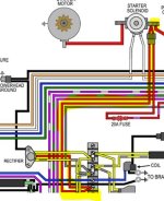
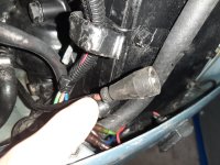
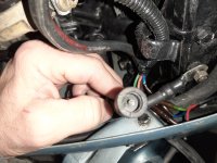
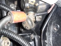
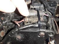
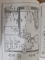
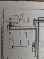
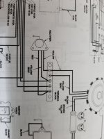
I have an 1986 evinrude 70 hp 3 cylinder. Not sure if rectifier is hooked up correctly. I only have a seloc manual and don't completely trust the diagram. Anyone confirm which wires the 2 yellow and 1 red wire connector to on the terminal block? It is new to me so just making sure things are wired correctly. Thanks
 

saltchuckmatt

Lieutenant Commander
Joined
Jul 19, 2019
Messages
1,818
Should just be 3 wires off the rectifier....one yellow one goes from the yellow off the rectifier to yellow under the flywheel, and one yellow/gray stripe to the yellow gray stripe....and red to red.

Pretty sure that's right. Can you still read the color codes of the wires?
 

maineiac5586

Senior Chief Petty Officer
Joined
Feb 14, 2009
Messages
657
Should just be 3 wires off the rectifier....one yellow one goes from the yellow off the rectifier to yellow under the flywheel, and one yellow/gray stripe to the yellow gray stripe....and red to red.

Pretty sure that's right. Can you still read the color codes of the wires?
That's the problem. The wires on the new rectifier are readable but the motor wires not too much. Where does the red wire come from?
 

saltchuckmatt

Lieutenant Commander
Joined
Jul 19, 2019
Messages
1,818
That's the problem. The wires on the new rectifier are readable but the motor wires not too much. Where does the red wire come from?
I believe the red wire comes from the starter solenoid....that is the return path to charge your battery.

Is there a red wire coming from the battery side of the solenoid?

Rectifier converts ac power to DC power.
 

Crosbyman

Vice Admiral
Joined
Nov 5, 2006
Messages
5,042
THe 2 yellows are AC voltage from above (flywheel) the 2 AC go on the 2 AC pins of the rectifier or need to match up with 2 yellows FROM the rectifier...

the RED has stated... comes from the starter solenoid BATTERY SIDE NOT the STARTER SIDE.... and is connected to the DC outpout of the rectifier or... the red output wire from the rectifier if any.


see "typical rectifier hook up using 2 yellows one red this is a two phase AC installation

...sometimes engines have 3 Yellows and need a THREE PHASE rectifier with 3 Yellow input and one RED output (not your case just FYI)


Some rectifiers also REGULATE their outputs to keep a steady voltage to charge batteries and not fluctuate to a point of causing shutdowns on electronic gear like depth sounders

you should acquire a good service manual
 

Attachments

  • typical rectifier  with 2 Yel one Red.JPG
    typical rectifier with 2 Yel one Red.JPG
    51.9 KB · Views: 5
Last edited:

maineiac5586

Senior Chief Petty Officer
Joined
Feb 14, 2009
Messages
657
I have a red wire that ends with an open socket single pin connector. It goes from the red rectifier connection point on the terminal block and runs to the port side near the solenoid. I must be missing another piece of that to connect to the solenoid? Motor runs fine but not charging
 

Crosbyman

Vice Admiral
Joined
Nov 5, 2006
Messages
5,042
the rectifier ouput must reach the solenoid to pass it's output voltage and current to charge the battery...

can't address your issue but find out why the rectifier is not connected to the solenoid post where the batt +12 is connected.
 

saltchuckmatt

Lieutenant Commander
Joined
Jul 19, 2019
Messages
1,818
I have a red wire that ends with an open socket single pin connector. It goes from the red rectifier connection point on the terminal block and runs to the port side near the solenoid. I must be missing another piece of that to connect to the solenoid? Motor runs fine but not charging
See what voltage your getting there.
 

maineiac5586

Senior Chief Petty Officer
Joined
Feb 14, 2009
Messages
657
the rectifier ouput must reach the solenoid to pass it's output voltage and current to charge the battery...

can't address your issue but find out why the rectifier is not connected to the solenoid post where the batt +12 is connected.
This is the wire that was currently hooked up to the red wire from the rectifier (at the terminal block). The rubber half a connector is just loose not connected to anything but is located near the starter and solenoid
 

Attachments

  • 20221228_205252.jpg
    20221228_205252.jpg
    3.4 MB · Views: 3
  • 20221228_205220.jpg
    20221228_205220.jpg
    3.4 MB · Views: 3

maineiac5586

Senior Chief Petty Officer
Joined
Feb 14, 2009
Messages
657
I still have a connector with a fuse in it connected to the 12v battery post on solenoid
 

Attachments

  • 20221228_205648.jpg
    20221228_205648.jpg
    4.1 MB · Views: 4
  • 20221228_205639.jpg
    20221228_205639.jpg
    3.5 MB · Views: 4

maineiac5586

Senior Chief Petty Officer
Joined
Feb 14, 2009
Messages
657
According to the wiring diagram I don't see anything coming off starter solenoid that would connect back to red rectifier wire
 

Attachments

  • 20221228_211102.jpg
    20221228_211102.jpg
    1.7 MB · Views: 5
  • 20221228_211107.jpg
    20221228_211107.jpg
    1.3 MB · Views: 5
  • 20221228_211116.jpg
    20221228_211116.jpg
    1.3 MB · Views: 5

racerone

Supreme Mariner
Joined
Dec 28, 2013
Messages
36,368
There is a 12 volt power supply ( fused ) that goes to the ignition switch.-----Comes off the solenoid.----What manual does the wirinh diagram come from ??
 
Last edited:

maineiac5586

Senior Chief Petty Officer
Joined
Feb 14, 2009
Messages
657
There is a 12 volt power supply ( fused ) that goes to the ignition switch.-----Comes off the solenoid.
So I guess I can cut that open plug off the red wire and hook it to the 12v battery post of the solenoid and I should be ok?
 

racerone

Supreme Mariner
Joined
Dec 28, 2013
Messages
36,368
Stop-----Wiring can be simple and yet so confusing !-----I suggest you consult a factory wiring diagram !
 

racerone

Supreme Mariner
Joined
Dec 28, 2013
Messages
36,368
Post an actual picture of the #4 and #5 terminals on your motor terminal strip !----Do not guess with wiring as it can be a smoky / expensive lesson.
 

Crosbyman

Vice Admiral
Joined
Nov 5, 2006
Messages
5,042
In this other version of a 1980 engine you can see the 2 yellows feeding a rectifier whose output (RED) works it's way back up to join up on the solenoid/battery wire.

The above posted JPGs do not show this very clearly because the red output takes a different path but the end result must be a return feed to the battery .

on the JPG's the terminal block where the RED rectifier goes... it is possible that post 4&5 are common (bridged) allowing the rectifier to reach the solenoid post via the 2nd left most wire comming off post#4 of the terminal strip. sometimes a link can be used to join the 2 wires.

in any configuration the rectifier output needs to reach the battery if charging is hoped for.

 
Last edited:

saltchuckmatt

Lieutenant Commander
Joined
Jul 19, 2019
Messages
1,818
I think you will find 2 & 3 are jumped together and 4 and 5 are tied together as well.

I think maybe your missing the other half of the plug that ran back to the soleniod. Is it heading that way?

Again, check voltage there while running.

Another thing, check for continuity between 4 and 5
 

maineiac5586

Senior Chief Petty Officer
Joined
Feb 14, 2009
Messages
657
I think you will find 2 & 3 are jumped together and 4 and 5 are tied together as well.

I think maybe your missing the other half of the plug that ran back to the soleniod. Is it heading that way?

Again, check voltage there while running.

Another thing, check for continuity between 4 and 5
I think you are right I am missing the other half of the plug that would go to the solenoid. Yes that red wire runs close to the solenoid. I will check for voltage in a couple days when I get a chance to fire it up
 
Top