470 mercruiser rebuilt engine install questions

aarons 470

Petty Officer 1st Class
Joined
Aug 29, 2012
Messages
351
Just a progress picture. Wish I could upload better quality pics. Ot won't let me.
 

aarons 470

Petty Officer 1st Class
Joined
Aug 29, 2012
Messages
351
Going through manual again. So on the flywheel cover stud, I was looking at wrong picture. It's a regular stud there's no nut built in. So a bolt should work fine? I cleaned off All paint at mating surface.

Can this be a major ground, or more for smaller
Grounds?

Where are the 1 or 2 main ground spots on the block for the batteries? Or is flywheel cover
Ok, the wire loom would be against the cover
Though, not actually against engine block. But the ground would flow through the bolts to the block. Is this ok?
 

alldodge

Moderator
Staff member
Joined
Mar 8, 2009
Messages
40,860
Cool thanks. Can I ground stuff to the flywheel cover? Bolt goes Into block.
Or does it have to be directly in the block?

Flywheel cover is ok

Manual shows a ground stud going through flywheel house with a nut in the center. All I have are bolts. Do I need to pick up that stud?

It is best to use a stud, reason is the stud allows to proper torque to be used to secure the flywheel. Using a bolt with the wire lugs under it puts soft meatal and copper under it. You want steel to steel for correct torque

Do you guys know where I can find a detail for the trim sender? the electrical main drawing we have been using just shows 2 connection points. I have 3, plus the ground. Not sure where my trim sender wire should hook to.

The sender should only have two wires, post a pic so we can see what you have

Green goes from sender to lift motor

Green and white goes from sender to small harness below sender.

Your starting to make my head hurt. Your previous post said the Green wire went to pin 8, and in that case it would be oil pressure. Or is this another Green wire? If it is another Green wire then it should have a white stripe.

The pic below is the power trim system. It appears to be the basic system which uses two solenoids, one up and one down.

fetch


Larger red wire goes from sender to another actuator? Not sure what it's called.

Is the sender the solenoid looking thing in front of picture? There's is another one that looks different to the left, it's a brown plastic.

The green wires and red wire come of the one in front with silver top.
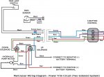
This is the trim system and the wiring diagram is below

Power Trim 2 Solenoid.jpg

Ok another important one. So the yellow red that comes of right side of slave that's attached to block and goes to starter slave.

Does that wire go to the S or the R on the starter. slave?

And what gauge do you recomend on this?
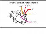
Yellow/Red should be 12AWG from the starter to the slave
Starter connect.jpg
Going through manual again. So on the flywheel cover stud, I was looking at wrong picture. It's a regular stud there's no nut built in. So a bolt should work fine? I cleaned off All paint at mating surface.

Can this be a major ground, or more for smaller
Grounds?

Where are the 1 or 2 main ground spots on the block for the batteries? Or is flywheel cover
Ok, the wire loom would be against the cover
Though, not actually against engine block. But the ground would flow through the bolts to the block. Is this ok?

The entire block is ground and the main ground (negative cable) from the battery can be attached anywhere on the block or flywheel so long as it is tight and of sufficient size. Use a stud which is close to the same size as the hole in the battery cable. Any other screw or bolt can be used to ground anything else so long as it is attached to the motor.
 

aarons 470

Petty Officer 1st Class
Joined
Aug 29, 2012
Messages
351
Thanks.
Yes those are different green wires. I thought that trim system would get the (pin 10) trim sender wire. So I was asking where it attaches. So I was looking in the wrong spot to hook up pin 10 trim sender wire.

What I was getting at is where does the trim sender wire (pin 10) connect to. probably a stupid question But I don't see a sender and haven't found it in the manual.
According to drawing you sent looks like its close to the throttle arm so ill just have to trace it out?

Everything looks good, just need to hook this up and the wire going to starter you just showed me. The yellow red from the block slave will go to small post "S" on the starter slave?

And on the drawing detail we have been using there isn't a purple yellow going to the starter slave. (like in this drawing you just gave me) do I need to bring (add) this over from the block salve? And that would go to the small post "R" on starter slave.

Sorry for the headache.:rolleyes: Appreciate all the info you've given me
 

alldodge

Moderator
Staff member
Joined
Mar 8, 2009
Messages
40,860
The trim gauge nor trim power circuit uses the 10 pin engine connector.

The Yellow/Red will go to the S terminal

The purple/yellow wire was not installed on your motor. This would only need to be added IF your were going to use an electric fuel pump.

Yes stainless hardware is OK to use, just don't use it for major connections link, flywheel to engine block, engine motor mounts, and the link. Use for holding small brackets, wire lugs and the like
 

aarons 470

Petty Officer 1st Class
Joined
Aug 29, 2012
Messages
351
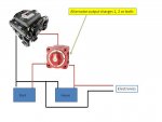
On the negative cables for the dual battery switch-
Directions say to run A negative cable from battery to battery.

I ran a negative from each battery to the same place on the block. is this sufficient or do I need to run another one that just goes from battery to battery?
 

alldodge

Moderator
Staff member
Joined
Mar 8, 2009
Messages
40,860
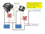
On the negative cables for the dual battery switch-
Directions say to run A negative cable from battery to battery.

I ran a negative from each battery to the same place on the block. is this sufficient or do I need to run another one that just goes from battery to battery?

No, either way is fine
 

aarons 470

Petty Officer 1st Class
Joined
Aug 29, 2012
Messages
351
Ok. Do you guys like to run your accessories to the common in the switch or do you run your accessories to either of the batteries?
 

aarons 470

Petty Officer 1st Class
Joined
Aug 29, 2012
Messages
351
I found this on a previous thread. so ill run it all to the common.
Later on when I add accessories, like down riggers/ radio etc Will I want to go to the common as well, or directly to a battery?

Re: Best way to wire my boat with dual batteries

ALL accessories (meaning everything currently connected to the +12 volt buss system) get connected to the COM terminal on the switch. This allows the most versatility for the entire system. You can start the engine on BAT 1, BAT 2, or BOTH if you like. You can operate accessories from BAT 1, BAt 2 or BOTH if you like, and you can charge BAT 1, BAT 2 or BOTH if you like depending on what switch setting you use. You NEVER power accessories other than the console instruments from the ignition switch. That switch is not capable of handling high current loads. Besides, the source of power for that circuit would be from whatever battery you have selected, then to the engine, then up the engine harness, through the ignition switch to the accessories on too small a wire. Here is how you do it. The only thing not shown is the heavy gauge wire (#8 or 10 gauge) from the COM terminal to the fuse or cirucit breaker panel. Nothing other than a trolling motor or an automatic bilge pump should be connected directly to either of the batteries.
 

alldodge

Moderator
Staff member
Joined
Mar 8, 2009
Messages
40,860
Just to be clear, using the common on a battery switch is fine so long as your not talking about a common ground. The battery switch common should be used to combine or switch the battery to the motor to start, Using a battery switch to switch batteries so you can run accessories is not the best idea.

Two Bat one switch.jpg

Two Bat w ACR.jpg
 

achris

More fish than mountain goat
Joined
May 19, 2004
Messages
27,468
...On another note. How do you get your thread to pull up with the most current page first?

Been a while since I caught up with this thread, but noticed a question on the previous page, and I'd like to offer a 3rd answer....

Capture.PNG
 

aarons 470

Petty Officer 1st Class
Joined
Aug 29, 2012
Messages
351
I have another serious issue. Harmonic balancer is on. It is rubbing the gasket plate, Not good. Just barely touching. I can turn engine with ratchet, but there is friction from it. It's torqued on at 75 pounds.

It's all origional stuff from engine. I did find an old post guy had same issue and he had to shim the balancer/rotor He never really knew what caused it.

Another guy suggested could be the gasket thickness. I think that is probably it.

I am going to call machine shop. It is my origional crank, so I don't think it would mate on farther than before from being machined/polished

On my 1988 470 the gap is at least 1/4" so maybe the gaskets are ok to be thicker on the newer engines? It has a different looking balancer/rotor


I wired the common positive from switch to the starter. I'll keep main starting battery free from extra accessories.

All my extra accessories will run to the second battery.
 

aarons 470

Petty Officer 1st Class
Joined
Aug 29, 2012
Messages
351
Machinist said it isn't enough rubbing to be an issue. So I guess that's good news. And it wouldn't be the crank from machining.

So it's probably combination of new gasket thickness and new paint on cover and balancer/rotor

Much closer than my 88 engine that's for sure
 
Last edited:

aarons 470

Petty Officer 1st Class
Joined
Aug 29, 2012
Messages
351
Exchanger is in. Plumbing next.

I have an oil cooler filter assembly, should I install it?

I don't think my 88 parts engine had one. Unless they removed it? This engine had the larger 4" exchanger- which is now installed on the 1982 engine in boat.

This 1982 apparently did have the oil cooler assembly. Pretty sure it is the mcm 485

Do you guys know if the actual engine oil cooler and the power steering cooler are the same part? Look similar on drawing.

Another electrical Q. When I run power to the electric fuel pump-

I'd want this to work on both batteries, so if I switch batteries I'll always has power.

If I don't run it (accessories) to the common positive on the switch, where should I run it?
 

stonyloam

Vice Admiral
Joined
Mar 13, 2009
Messages
5,827
I believe the engine oil cooler is used with the 4 barrel carbureted engine, not the 2 bbl.
 

aarons 470

Petty Officer 1st Class
Joined
Aug 29, 2012
Messages
351
Agree; engine is a weird though. It has the larger cobra jet head according to my machinist. And the oil cooler assembly was with it when I bought boat.

And And it says 485 on the outdrive. I bought it from origional owner he didn't mention modifying anything. Maybe it was the experimental boat by glasply lol.

It also has the strange/rare flapper elbow assembly
 

alldodge

Moderator
Staff member
Joined
Mar 8, 2009
Messages
40,860
Power steering cooler and oil coolers are different and I would not interchange them. The oil cooler needs to flow more oil then the power steering.

It won't hurt to install a oil cooler with a caveat; You are positively certain that there was not an engine failure prior. If the prior engine had failed there could be small particles of metal in side the cooler. Flushing the cooler will not guarantee you get everything out of it. I don't see your motor putting out enough heat to need the cooler in any case.

What do you mean buy running power to the electric pump (the fuel pump)?
 

aarons 470

Petty Officer 1st Class
Joined
Aug 29, 2012
Messages
351
That's a really good point on the oil cooler having debris in it. Engine was out of boat so it may have had a failure of some sort. If oil cooler isn't needed I'd rather not install it or the assembly.

Yes on the electric fuel pump. It gets the switched power, and power straight from battery to relay then pump.
With the 2 battery setup- one battery has that main fuel pump positive wire attached.

If I flipped battery switch to battery 2, pump would loose the direct power?
 
Top