HeadAbove
Cadet
- Joined
- Jun 4, 2023
- Messages
- 15
Hi All,
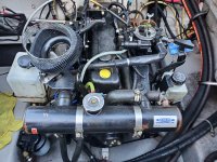
Mercruiser 3.0L (1A311803); Aftermarket closed cooling half-system; A1G2 drive.
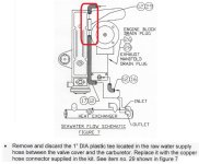
I'm trying to simplify my current hoses, routings and drain process, mainly because the PO who installed the aftermarket closed cooling system left some of the superfluous OEM fittings in place. (I've read the installation instructions to validate this.) And I think these pieces left behind are confusing me. So, a couple of questions:
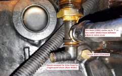
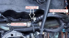
1) The raw water intake hose which runs from the transom to the aftermarket HE is a 2-piece hose with a "T" fitting in the middle. (Mercury p/n 32-862325.) The narrower, 24in long hose off the "T" routes down to another "T" fitting at the lower drain plug on the port side of the engine.
What is this hose for?
I was thinking maybe it's to hook-up a flush kit. Or maybe to allow the transom intake hose to drain with the rest of the sea water. But then I realized that the intake hose would drain naturally out of the transom whenever the sterndrive removed. So is the single purpose of this smaller hose to drain the intake hose whenever the sterndrive can't be removed from the boat?
I would really like to delete this "T" fitting from the raw water intake hose and just use a straight-through 1in hose coupler.
2) Again in the spirit of simplification, I want to remove what is left of the single-point drain system in my boat. I want to remove the handle bracket and the one remaining blue hose. (The other blue drain hose became obsolete with the closed cooling system.)
I will then replace the sea water quick drain/hose fittings with a stainless drain plug.
But I'm having trouble getting my head around which drain port is which...
...If there is sea water running through my exhaust manifold and coolant running through my cylinder block, why is the drain plug directly underneath the exhaust manifold now sealed-off (by a brass plug supplied in the closed cooling kit) and why do I get sea water out of the lower, block drain port?
In my mind, the port to drain the exhaust manifold of sea water should be the one right underneath the manifold and the block drain (coolant) would be the lower port on the block. But this appears to be the opposite of what I'm seeing.
Hopefully someone can tell me what I'm missing without making me feel too stupid.
Tks!


