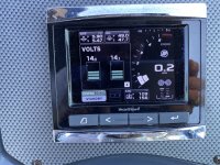
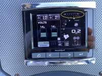
2016 Mercruiser 6.2 ECT - long beep every few minutes???

dingbat

Supreme Mariner
Joined
Nov 20, 2001
Messages
15,481
No, all seven batteries '-' terminals are connected together with very thick cable (Yellow). It is just hard to see in the pictures. I will double check so as to eliminate possibilities.

I am learning the wiring convention is this boat. . .

Red = Power source voltage
Gray = Switched Power (i.e. lights accessories, etc)
Yellow - Ground

One nice thing is that all wires are individually marked along their entire length with a reference number and brief description, so you can more easily trace the wiring over the length of the runs.

Cruisers Yacht also send me the harness & connector drawings, so I have begun to look at those to see if the engine systems are getting multiple power sources.
Pretty sure your chasing ghosts for the most part.

Went through the manual. Looks like nothing fancy. Typical I/O. Basic voltage monitoring although chassis (ground) is floating. Makes you sensitive to ground issues.

Has a 485 serial output. Wonder if that’s not feeding the display up front?

Measure the voltage on the pins at the connector on pcm with ignition on. Measure with two sources of ground to confirm common potentials.

I would also check to see what pins are populated in the connector to determine what inputs are being utilized. I suspect a lot of the data points are software generated.

I would also reset VV to clear alarms and reset the voltage parameters.

I don’t understand the 17 volt upper limit. Is that configured or measured?
 

tpenfield

Moderator
Staff member
Joined
Jul 18, 2011
Messages
17,693
Quick Update:

I tied the accessory battery and the starboard battery together. They were about 0.6 volts apart as I had suspected.

That change made a difference, but it was short lived. I got a few starts of the engines with no warnings, but then the voltage warning returned.

It does seem like a voltage supply issue. So, I’ll be checking the helm and engine bay both positive and ground connections to see if I can isolate the discrepancy.

I’ll post a few screenshots this evening. Thanks everyone for your inputs and suggestions.
 

muc

"Retired" Association of Marine Technicians...
Joined
Jul 7, 2004
Messages
2,064
All models need a minimum of 800 CCA, 1000 MCA, 180 Ah batteries.

IMPORTANT: For DTS products, each engine must be equipped with its own starting battery. If your boat application requires additional battery loads for boat accessories or marine electronics, it is recommended that an auxiliary battery or batteries be installed.


Multiple MPI Engine Battery Information Batteries: Boats with multi‑engine MPI power packages require each engine be connected to its own battery. This ensures that the engine's Electronic Control Module (ECM) has a stable voltage source. Battery switches: Battery switches should always be positioned so each engine is operating off its own battery. Do not operate engines with switches in BOTH or ALL position. In an emergency, another engine's battery can be used to start an engine with a dead battery. Battery isolators: Isolators can be used to charge an auxiliary battery used for powering accessories in the boat. They should not be used to charge the battery of another engine in the boat unless the type of isolator is specifically designed for this purpose. NOTE: Sure Power Industries Inc., Model 32023A meets this design specification. 1. The boat may have 2 engines connected to a single Model 32023A battery isolator. 2. The Model 32023A battery isolator is connected to 2 banks of batteries. 3. Each bank contains 2 batteries with the cranking battery for 1 engine in each bank. 4. The second battery in each bank is connected in parallel to the cranking battery. 5. The Model 32023A battery isolator is designed for this type of use; 2 battery banks, 2 charging sources, 120 amps (maximum alternator output). 6. When the engines are operating, either engine's alternator could be charging either bank of batteries through the Model 32023A battery isolator. Any other manufacturer's battery isolator that is the same type as the Sure Power Inc., Model 32023A could also be used. Generators: The generator's battery should be considered another engine's battery.


Helm main power relay (MPR) harness connection—This harness connects the helm harness to the circuit protected switched starboard battery power, only used on the starboard side. The helm MPR harness supplies this heavy power to the starboard helm CCM main power relay. This power is primarily used for steering wheel centering. This harness connects to a fused power and ground supplied by the boat builder. Does the Cruisers wiring diagram show this connection at the helm? Sometimes the boat builder will use the house battery for this and that can lead to the problems you’re experiencing.

From the install manual,

Main Power Relay (MPR) Harness Connections for Mercury Propulsion System Components

1. Positive

a. Standard positive connection: Install a 20‑amp circuit breaker or 20‑amp ATC fuse for the positive circuit of the main power relay harness on the switched side of the appropriate engine cranking battery system.

b. Optional positive connection: The main power relay (MPR) harness does not have circuit protection or wire terminals on the end of the harness that connects to the power source. Therefore, the builder must provide an in‑line circuit breaker or fuse and the necessary wire terminals to connect the harness to the DC power bus.

NOTE: Refer to the main power relay harness instruction sheet for recommended connection points.

2. Ground
a. Standard ground connection: Connection of any required MPR grounds should be made directly to the negative post of the associated system’s cranking battery.

b. Optional ground connection: Connect the ground directly to the main vessel DC ground bus. The main ground bus must be part of the engine cranking ground path. The connection should be connected directly to the bus and should carry no other loads between it and the cranking ground bus connection.

IMPORTANT: Connection to auxiliary vessel ground paths not carrying cranking ground current is specifically not allowed.


Some questions about your boat.

This is part of what my problem is.

For diagnostic troubleshooting and parts identification, it is often necessary to determine which version of Axius is present on the boat. Axius Gen 1 and Gen 2 may be easily discerned by their hardware and physical differences. However, Axius Gen 2 and Axius Joystick Piloting for Sterndrives (JPS) look physically identical and may only be identified by their engine serial numbers. CDS G3 can be used to positively identify all versions of Axius by the matching eBOM.I’m not able to I.D. your system by the serial number and G3 isn’t a option. So I’ll ask these question.


From reading your posts, it appears that you have electronic steering, electronic throttles, vesselview4 and joystick. Is this correct?

Can you post a picture of your throttle and shifters?

Do you have a trackpad that allows you to engage features like, Skyhook, Waypoint Sequencing, Auto Heading, Troll, Engine Synchronization, Docking Mode, Throttle Only and Single‑Lever Mode? Do you have any of these features and how do you access them?

Do you know if you have Axius Joystick Piloting basic or Axius Joystick Piloting premier?

Do you have “multiwake”? This is a feature that among other things sends power to both engine gauge packages when just one of the keys is turned on.

Do you have a Fire Suppression system that shuts down the engines if the halon bottle goes off?

Do you have a start/stop panel with push buttons or just key switchs?

What style of Lanyard Stop switch installed? Maybe post a picture?

What is the part number of the PCM 112 diagnostic manual you have?

Sorry for all these questions but with me not being on the boat I just don’t know. These are all questions that a trained tech sees when they climb aboard.

If you start messing around under the dash, know that all the really important connectors (steering, throttles and shift) will have a feature known as connector position assurance (CPA) clip. Make sure you disengage this clip before separating the connectors and you won’t be able to engage the clip until both connectors are fully together. Be careful when checking this stuff. Your computers stay “awake” for a few minutes after you turn the keys to off and can stay awake after the battery switches are turned off. This is because the clean power is on all the time. So unless you know what fuses to pull, it’s best to disconnect ALL the batteries ground cables otherwise it’s possible to fry a computer and you have more than a few on this boat! Also be careful when probing the connecters, there is a set of special probes we use to keep from deforming all these connectors.

Do NOT connect multiple batteries together, if you suspect an issue with batteries. Load test them or replace them. Never run the boat with the switches set to all.

Clean Power Connections for DTS and ECT engines

Mercury clean power harnessing must be connected directly to the positive and negative posts of the corresponding propulsion engine's cranking battery.

IMPORTANT: Any deviations from the clean power connection requirement must be approved by Mercury Marine.

I’m not sure if I was clear about clean power, this is a separate power connection to the engine battery. As outlined above it is a 2 wire harness with a inline fuse (can be 5amp, 7amp or 20amp depending on what systems are installed) near the battery that connects to the engine near the power post that the big battery cable connects to with a 2 wire connecter. It also might be near the back of the engine by the 14 pin can connection and the transom harness connector.

Answers to some of your questions, let me know if I missed any or you would like a better explanation.

G3 is the only tool that can see all the different components of this system. But it’s only available to Mercury Marine dealers. ---- It’s hard for me to not get started on “Right to Repair’ legislation. I just ask that we DIY people keep this in mind when voting for the people who make the laws! ---- sorry but some things bother me. That said Diacom is what you have and it’s the best substitute for G3 that’s available. Just remember that there are something’s it can’t do.

You are seeing different data streams. Your engine has 2 connection points on the engine. The one to the right of the main circuit breaker is the J1939 diagnostic connection. The one to the left of the circuit breaker is the 10‑pin diagnostics can bus connector like the one at the helm.


Wow that’s a lot of info and I’ve run out of time for this post, I’m going to have to post it without proof reading. Let me know if there are any mistakes or questions.
 

alldodge

Moderator
Staff member
Joined
Mar 8, 2009
Messages
40,714
Thanks MUC that is a lot of info and a lot of work on your part
 

tpenfield

Moderator
Staff member
Joined
Jul 18, 2011
Messages
17,693
Yes, @muc Thank you for posting the information. I will be reading through it.

FWIW - The system warnings not seem to be hit or miss. We went to our favorite anchoring spot today. On the way over the engines had the warning. On the way back the engines said the were 'OK'. Once at the off-loading dock and restarting the engines, it gave the warning again.

As I have time over the next few days, I'll do some more probing of the power at the helm.

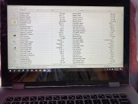
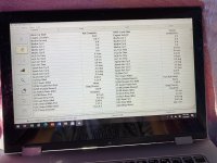
Here are some screen shots
IMG_3435.JPGIMG_3438.JPGIMG_3439.JPG
 

tpenfield

Moderator
Staff member
Joined
Jul 18, 2011
Messages
17,693
@ Muc Here are the answers to the questions as best that I have them right now. I'll get more info over the next 1-2 days.

From reading your posts, it appears that you have electronic steering, electronic throttles, vesselview4 and joystick. Is this correct?
Yes Correct

Can you post a picture of your throttle and shifters?
Will get a picture soon

Do you have a trackpad that allows you to engage features like, Skyhook, Waypoint Sequencing, Auto Heading, Troll, Engine Synchronization, Docking Mode, Throttle Only and Single‑Lever Mode? Do you have any of these features and how do you access them?
There is an Axius control panel with shyhook and a bunch of other things. I'll get a picture. The DTS has 'throttle only' and some of the other features


Do you know if you have Axius Joystick Piloting basic or Axius Joystick Piloting premier? Not sure The manual that came with the boat says Gen2

Do you have “multiwake”? This is a feature that among other things sends power to both engine gauge packages when just one of the keys is turned on. Don't know

Do you have a Fire Suppression system that shuts down the engines if the halon bottle goes off? There is a fire suppression system, (FireBoy) not sure if it shuts the engines down.

Do you have a start/stop panel with push buttons or just key switchs?
Key Switches

What style of Lanyard Stop switch installed? Maybe post a picture?
No Lanyard


What is the part number of the PCM 112 diagnostic manual you have?
I have found bits and pieces, but i do mot have the PCM manual.

I'll post more info (pics) soon. Thank you
 

tpenfield

Moderator
Staff member
Joined
Jul 18, 2011
Messages
17,693
@muc More replies below . . .

Multiple MPI Engine Battery Information Batteries:

Boats with multi‑engine MPI power packages require each engine be connected to its own battery. This ensures that the engine's Electronic Control Module (ECM) has a stable voltage source. - - > each engine has its own battery, there is a ‘Parallel’ momentary switch that can be used for starting the engine(s) with a weak/drained battery.

Battery switches: Battery switches should always be positioned so each engine is operating off its own battery. - - > Yes

Do not operate engines with switches in BOTH or ALL position. In an emergency, another engine's battery can be used to start an engine with a dead battery. - - > No ‘BOTH’ setting on battery switches . . . each engine has its own switch that is ON/OFF.

Battery isolators: Isolators can be used to charge an auxiliary battery used for powering accessories in the boat. They should not be used to charge the battery of another engine in the boat unless the type of isolator is specifically designed for this purpose. - - > Isolators are used for the INVERTER battery bank (4 batteries) and the ACCESSORY battery. I am not sure if one engine can/cannot charge the battery of the other engine. I will see if I can verify.

NOTE: Sure Power Industries Inc., Model 32023A meets this design specification. 1. The boat may have 2 engines connected to a single Model 32023A battery isolator. 2. The Model 32023A battery isolator is connected to 2 banks of batteries. 3. Each bank contains 2 batteries with the cranking battery for 1 engine in each bank. 4. The second battery in each bank is connected in parallel to the cranking battery. 5. The Model 32023A battery isolator is designed for this type of use; 2 battery banks, 2 charging sources, 120 amps (maximum alternator output). 6. When the engines are operating, either engine's alternator could be charging either bank of batteries through the Model 32023A battery isolator. Any other manufacturer's battery isolator that is the same type as the Sure Power Inc., Model 32023A could also be used.
- - - > I will check the isolators to see if they meet the requirements

Generators: The generator's battery should be considered another engine's battery. - - > No generator, only an inverter


Helm main power relay (MPR) harness connection—This harness connects the helm harness to the circuit protected switched starboard battery power, only used on the starboard side. The helm MPR harness supplies this heavy power to the starboard helm CCM main power relay.

This power is primarily used for steering wheel centering. This harness connects to a fused power and ground supplied by the boat builder. - - > There have been ‘wheel faults’ usually when I turn the wheel to its stop point. The steering angle indicator on the VesselView Display does not seem to be working and is at 45˚ to starboard.
.
IMG_3435-B.jpg

.
Does the Cruisers wiring diagram show this connection at the helm? Sometimes the boat builder will use the house battery for this and that can lead to the problems you’re experiencing. - - > I don’t have all if the wiring diagrams (it seems) so I’ll have to trace out the helm wiring to see where the engine system power is coming from. (I am thinking that this may be the issue and it surfaces when the ‘house’ battery becomes weaker than the engine battery)
 

tpenfield

Moderator
Staff member
Joined
Jul 18, 2011
Messages
17,693
One other thing of note . . .

In my testing, I have noticed that if I turn off the Starboard engine battery there is a slight buzzing that comes from the area of the relays on the top of the engine. (I had the cowls off so I could hear where the noise was coming from).

If I turn off the Accessory (house) battery the buzzing stops . . . or . . . if I turn the starboard battery back on the buzzing stops.

This has led me to think that the house battery has been wired to power some of the engine systems at the helm.
 

nola mike

Vice Admiral
Joined
Apr 22, 2009
Messages
5,062
1. Have you tried disconnecting all batteries except engine batteries?
2. Have you been able to get screenshots of the voltages when the fault isn't present?
3. Was this problem there on the sea trial or did it show up after you got the boat?
 

tpenfield

Moderator
Staff member
Joined
Jul 18, 2011
Messages
17,693
1. Have you tried disconnecting all batteries except engine batteries?
2. Have you been able to get screenshots of the voltages when the fault isn't present?
3. Was this problem there on the sea trial or did it show up after you got the boat?
See my answers below . . .

1. Have you tried disconnecting all batteries except engine batteries?
I have not, but it would be a good test of my theory on the helm power. I am wondering if I can/should just shut of the house and inverter batteries or actually disconnect them for the test? :unsure:

2. Have you been able to get screenshots of the voltages when the fault isn't present?
Yes, some of them have been posted. Voltages are not all that different, if at all.

3. Was this problem there on the sea trial or did it show up after you got the boat?
It was present at the Sea Trial, but I had the PO fix some more significant issues, figuring the low voltage would not be a big deal (wrong . . . :ROFLMAO: )

FWIW - When I had the boat on Shore power, the issue was not present. Currently the issue is there sometimes and not other times.
 

tpenfield

Moderator
Staff member
Joined
Jul 18, 2011
Messages
17,693
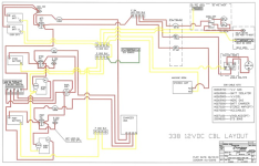
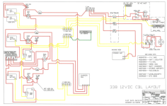
This is a little hard to read, but here is the power wiring diagram of the boat that I got from CY tech support..
.
CY-338-PowerCable-Diagram.png
.
One difference I have noted is that I have only 1 Accessory battery rather than the 2 batteries shown.
 

tpenfield

Moderator
Staff member
Joined
Jul 18, 2011
Messages
17,693
Following up on one of the questions about if either engine can charge the batteries. . . .

It looks like there is a 2 alternator, 3 battery isolator in the wiring diagram. So, It would seem that either engine can be the source of charging power to the engine and accessory batteries.

The inverter batteries charge off the port engine only via an isolator.
 

muc

"Retired" Association of Marine Technicians...
Joined
Jul 7, 2004
Messages
2,064
First thing I would do is get a big bag of tie straps and a pair of side cutters. Take as many pictures of your engines, with special attention to the back and transom. Starting at the clean power connector on the stbd engine. Follow the clean power harness to where ever it goes. Probably going to have to cut 20-40 tie wraps to do this. Try to replace these tie wraps as you go. There are a lot of harnesses going every where on the back of the engine and it’s important that they go back in about the same places. Don’t want them getting snagged on the steering. Do the same for the port engine. Both of those clean power harnesses need to connect directly to their respective starting battery.

Looking at the wiring diagram. The post next to the stbd batt switch marked S ISO POST is my guess where the helm power should be connected. I see Cruisers lists a cable kit for V. V. Gas, vesselview gas? Maybe be labeled on the harness.

Has the rudder indicator always read 45* stbd? That should be throwing a fault!
I’ll have to think about the buzzing, but yes it stopping when you when you turn the house off sure seems to point to something being connected wrong.

Might not hurt to call Cruisers and ask if Mercury gave them permission to connect clean power somewhere other than the battery and if they know where the V. V. Gas cable kit is supposed to be connected.
 

muc

"Retired" Association of Marine Technicians...
Joined
Jul 7, 2004
Messages
2,064
P.S.
Once you go through this harness tracing. You will want to buy a pair of “flush cutting” side cutters. There will be blood😀
 

muc

"Retired" Association of Marine Technicians...
Joined
Jul 7, 2004
Messages
2,064
I forgot about your trim sender question, here’s what needs to be done when replacing a digital trim sender.

Trim Adaptation Process


2. With the engine off (not running) and the ignition key switch in the "RUN" position, use

the control handle trim switch to trim the engine all the way down/in. When the engine

reaches the bottom most point (stall) the trim motor will have a noticeable change in

sound. Hold the switch for three seconds. This will adapt the PCM to the bottom most

point of the sensor travel.

IMPORTANT: The following step should only be completed if there are no obstructions

preventing the engine from trimming to its upper-most trim position or if the Max Trailer

Limit is not going to be set.

3. With the engine off (not running) and the ignition key switch in the "RUN" position, use

the control handle trim switch to trim the engine all the way up/out. When the engine

reaches the upper-most trim position, the trim motor will stall. This step does not require

a three second stall to adapt. If the engine can not be tilted to the top of its travel due

to an obstruction (swim platform, engine well, etc.) trim only to the highest point without

hitting.
 

tpenfield

Moderator
Staff member
Joined
Jul 18, 2011
Messages
17,693
Thanks for your comments and assistance @muc and others (y)

I have contacted CY Tech Support (via email) regarding the helm power, and have also asked for the diagrams for the V.V. Gas and the Merc Gas cable kits. Those don't seem to be in what they already sent me.

I have not noticed how long the steering indicator has been at 45˚ starboard. But it has been for as long as I have been chasing the voltage issue. There have been a few 'wheel faults', but nothing consistent or codes.

I do notice on the 12 VDC power diagram, they indicate that the Port ISO Post is not used on VesselView optioned boats. So, it may be an indication that they are using the Starboard ISO Post.

I did buy a 'lifetime' supply of cable ties a while back, and it is quickly becoming depleted :ROFLMAO: . . . still plenty left though. I'll see what I can trace from the back of the engines.

I'll also look in my manual(s) to see if there is a way to reset the steering indicator. (Electronic steering scares me 🤪 , but I guess that is the only way to get the joystick type of controls.)

I also plan on checking voltages and resistance (to ground) in as many places as possible. If the engine controls are using the helm power to some extent, I noticed that the wiring takes the feed through quite a few connections/beakers, terminals, etc. Lots of places to loose some voltage.

For all the talk about engines with CATs (catalytic converters), it seems like most of the complexity has nothing to do with the CATs. More so all the fancy control stuff, than the CAT aspect.

Although Cruisers Yachts has fairly complex wiring, their electrical workmanship seems quite good. So, I'm hopeful not to find bad connections, etc. Some of the Mercruiser wiring, I'm not in love with . . .

The extended family is visiting for the week . . . Today, the dog gets to go on the boat and use his special doggy ladder for re-boarding.
.
Ragnar-Boat.jpg
.
I may have some time later today to start checking things out regarding the helm wiring.
 

tpenfield

Moderator
Staff member
Joined
Jul 18, 2011
Messages
17,693
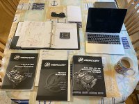
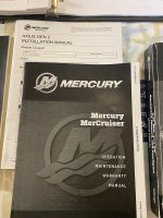
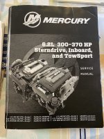
Here is my morning reading . . . 100's of pages of gripping dialogue. I mostly look at the pictures :ROFLMAO:

For any question on the manuals, versions of stuff, etc. Here is what I got. Some came with the boat and some I've acquired.
.
IMG_3444.JPG
.
IMG_3445.JPGIMG_3445.JPG
.
IMG_3446.JPG
.
IMG_3447.JPG
.
IMG_3448.JPG
.
 

tpenfield

Moderator
Staff member
Joined
Jul 18, 2011
Messages
17,693
As for the steering angle indicator, which does not seem to be working, I believe there is a steering angle source selection in the VesselView settings menu. . . . PCM0, PCM1, PCM2, etc and TVM. I will try different choices to see if it makes a difference.
 

muc

"Retired" Association of Marine Technicians...
Joined
Jul 7, 2004
Messages
2,064
Please post pictures of your helm when you get a chance.
multiwake, when you turn just the stbd key on does the port gauge wake up?
fireboy, do you have an override switch or just the green light?
does your joystick work? If it does that would mean that the steering angle is just a display issue.
You posted a Diacom screenshot of the port engine. The stbd engine is the master engine, it’s the one that processes the all the helm, steering and shift data. The port engine is the slave and is basically just along for the ride. It’s good that the port charge’s the inverter bank. I would be interested in how that’s wired. Do you know if the inverter was a Cruisers installed option or was it added later? Sometimes one way to tell is whether or not you can run the water heater or battery charger with the inverter. A quality inverter install won’t allow you to do that.

Enjoy the time with family!
 
Top