2008 Chaparral 275 SSI 8.1 Volvo Penta GXI-J Soft Alarm Issues

Nheels

Petty Officer 2nd Class
Joined
Mar 8, 2021
Messages
119
I'll give that a shot. Just ran the serial number through the VP site and it just gives year of manufacture range (07-09) and year of commision..urg.
 

Donald0039

Chief Petty Officer
Joined
Jun 11, 2022
Messages
402
You can call or email Rinda very helpful. Find the connector on your engine and take a picture. My connector has rubber kind of plug/cover to keep things out (leaves, water, etc).

I bought an 11" Acer laptop to use with the Rinda and OBDII scanner for my car. It was $400. I'd prefer my good home laptop (with lots of important stuff on it) not go boating.

Depending upon local marine mechanics, one may need to learn to do a lot of their own work if they have a Volvo Penta I/O. Around southern Delaware it's outboards.

Order the engine and outdrive manuals from VP. Print the ones you can. Some you you have to buy. Shipped from Sweden.
 

apisk

Petty Officer 3rd Class
Joined
Jun 17, 2023
Messages
82
Looks like your correct, but have also noticed some VP models have had 2 different connectors for the data link. Not saying one is better then the other but just what I've come across
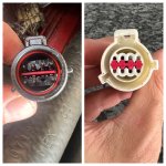
Interestingly enough the connector that I bought an adaptor for was not the right one. To the untrained eye, it looked identical, but it's only identical looking straight at it, which does not actually line up when trying to connect them (the one portion at 3 o clock of the circle and other at 8 o clock don't align). Will have to wait til they open on Wednesday to call and order the adaptor (94029) for the other connector that my boat has (pictured separately below)IMG_7194.JPGScreen Shot 2023-07-03 at 1.14.58 PM.png
 

Nheels

Petty Officer 2nd Class
Joined
Mar 8, 2021
Messages
119
Interestingly enough the connector that I bought an adaptor for was not the right one. To the untrained eye, it looked identical, but it's only identical looking straight at it, which does not actually line up when trying to connect them (the one portion at 3 o clock of the circle and other at 8 o clock don't align). Will have to wait til they open on Wednesday to call and order the adaptor (94029) for the other connector that my boat has (pictured separately below)View attachment 383254View attachment 383256
I've been emailing them and they replied that the J series (even though mine were made in 2007) takes the CAN style as you just found out. In my opinion, we are lucky as that is the upgraded one is my understanding. I think it fits more applications too?
 

Donald0039

Chief Petty Officer
Joined
Jun 11, 2022
Messages
402
Interestingly enough the connector that I bought an adaptor for was not the right one. To the untrained eye, it looked identical, but it's only identical looking straight at it, which does not actually line up when trying to connect them (the one portion at 3 o clock of the circle and other at 8 o clock don't align). Will have to wait til they open on Wednesday to call and order the adaptor (94029) for the other connector that my boat has (pictured separately below)View attachment 383254View attachment 383256
Hopefully you can return the one that does not fit and get a refund.
 

alldodge

Moderator
Staff member
Joined
Mar 8, 2009
Messages
42,068
That's a bummer, hope they will exchange
The CAN connector is the other that one I was thinking of which another poster posted here prior. I'll try to put this in my notes for when it shows up again
 

apisk

Petty Officer 3rd Class
Joined
Jun 17, 2023
Messages
82
That's a bummer, hope they will exchange
The CAN connector is the other that one I was thinking of which another poster posted here prior. I'll try to put this in my notes for when it shows up again
I spoke to a rep named Mark and he was super helpful. He said that the circular connector that I originally bought for is for connecting 2 engines. The 94029 is the correct adaptor for my setup and they are able to just exchange them (plus some money for price difference) as opposed to having to return everything and re-order. He was great to deal with, so I will report back once I get the new adaptor
 

apisk

Petty Officer 3rd Class
Joined
Jun 17, 2023
Messages
82
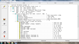
Update for all - finally got the right adaptor (I can confirm 94029 does work) and was able to run the Diacom software without even needing to take the boat out for a ride. It appears the previous trouble codes are listed (image below). I wonder if this is just a bad Knock Sensor or potentially something else. I am going to take it out for a ride just to confirm that is in fact what is being triggered, but at least we have some directionecmgrab_1.PNG
 

Attachments

  • ecmgrab_2.PNG
    ecmgrab_2.PNG
    184.5 KB · Views: 3
Last edited:

tpenfield

Moderator
Staff member
Joined
Jul 18, 2011
Messages
18,042
The first thing that strikes me is the Sensor Supply voltage #2. That voltage looks low, but I am wondering if it is the data from a previous fault. Perhaps you can post some of the current data, or even a recording of the data while the engine is running.

If you have a recording of the data while underway getting up to cruising speed and running for a few minutes, you could post it to Google drive (or similar and share the link to the file. So, some of us on the forum who have Diacom could could take a look. The files are not that big.
 

apisk

Petty Officer 3rd Class
Joined
Jun 17, 2023
Messages
82
I just took it out and recorded the live data, the alarm came on right around the 7:40 mark (I heard it and looked down and it said 7:44 so give or take a few seconds), I lowered speed to below 3000 RPM, it went away, pushed it again over 3000 RPM and came back on. Let me know if there's any issues accessing the file!


tpenfield

Moderator
Staff member
Joined
Jul 18, 2011
Messages
18,042
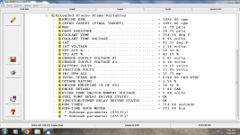
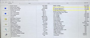
The 5V Sensor Reference #2 is low . . . 4.17 volts vs. 5.01 volts for the Reference #1. It would be best to get that fixed. It could be a faulty sensor bringing the voltage down.

Is there a trim sender that is not connected or not working?
 

apisk

Petty Officer 3rd Class
Joined
Jun 17, 2023
Messages
82
The 5V Sensor Reference #2 is low . . . 4.17 volts vs. 5.01 volts for the Reference #1. It would be best to get that fixed. It could be a faulty sensor bringing the voltage down.

Is there a trim sender that is not connected or not working?
Is the 5V sensor something different than the Knock Sensor which had low voltage too? If different, what would need to be fixed, or what sensor to look for?

The trim sender is connected and working, but the gauge does not work. Could that be related?

Did anything else stand out?
 

apisk

Petty Officer 3rd Class
Joined
Jun 17, 2023
Messages
82
Is the 5V sensor something different than the Knock Sensor which had low voltage too? If different, what would need to be fixed, or what sensor to look for?

The trim sender is connected and working, but the gauge does not work. Could that be related?

Did anything else stand out?
I also see the Soft Warning Output goes On/Off at the same time the alarm so it does recognize it when it happens, but it doesn't seem any of the other sections drop/raise dramatically?
 

tpenfield

Moderator
Staff member
Joined
Jul 18, 2011
Messages
18,042
The 5V sensor reference is not a sensor it is a voltage source for the sensors. If it does not read 5.0 volts, then the data (voltage) from the sensors using that voltage reference will be off. I am not sure which sensors are using VR #1 vs. VR #2

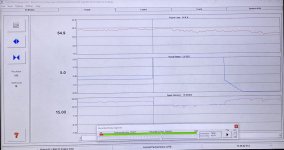
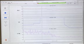
I see the knock retard going up to 5 degrees when the engine load is fairly steady. There was Knock Sensor 2 fault previously. Also an ECT fault and an EMCT (Exhaust riser) fault.

I think the think to do is figure our why/how/where the VR #2 is getting dragged down.

I do see the knock sensor kicking in and the knock retard going up to 5 degrees while the engine load is staying fairly constant. Don't worry about this until you get the Voltage References (VR) sorted out.
.
IMG_4966.JPG
.
IMG_4964.JPG
.
IMG_4965.JPG
 

tpenfield

Moderator
Staff member
Joined
Jul 18, 2011
Messages
18,042
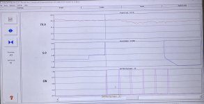
Here are your soft warnings . . . when the knock retard goes to 5 degrees.
.
IMG_4967.JPG
 

apisk

Petty Officer 3rd Class
Joined
Jun 17, 2023
Messages
82
Here are your soft warnings . . . when the knock retard goes to 5 degrees.
.
View attachment 384017
I ask these questions as a total newb, but is it possible that the VR#2 issue that you called out is feeding the Knock Sensor? You mentioned that we can't really tell which sensors use which VR, but is that one possibility?

The only reason I keep bringing up the Knock Sensor is the callout in the Codes section, so just want to rule it out or dig in on that
 

alldodge

Moderator
Staff member
Joined
Mar 8, 2009
Messages
42,068
If there actually is a knock being sensed then that is an issue. Look for the sensor on the side of the block, will have a singal wire and larger plastic type connector

Follow the wire and make sure it is not in a bundle with the spark plug wires. The plug wires if they are side by side will send a false signal to the ECM

Do agree the 5V needs to be fixed
 

tpenfield

Moderator
Staff member
Joined
Jul 18, 2011
Messages
18,042
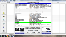
Not sure which ECM/PCM your engine has . . . Which ECM are you having to chose on the Diacom screen?
 

apisk

Petty Officer 3rd Class
Joined
Jun 17, 2023
Messages
82
If there actually is a knock being sensed then that is an issue. Look for the sensor on the side of the block, will have a singal wire and larger plastic type connector

Follow the wire and make sure it is not in a bundle with the spark plug wires. The plug wires if they are side by side will send a false signal to the ECM

Do agree the 5V needs to be fixed
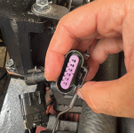
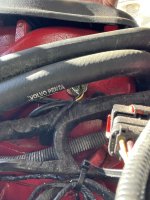
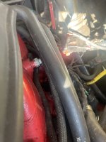
I followed the wire and it goes to the back of the engine, so not near or tied in with the spark plug wires - there was one sensor right at the rear/top of the engine that had wires which were pretty squished by a larger hose, which sensor is this?
 

Attachments

  • IMG_7285.jpeg
    IMG_7285.jpeg
    1.3 MB · Views: 5
  • IMG_7283.jpeg
    IMG_7283.jpeg
    1.7 MB · Views: 5
Top