2007 Yamaha F50TLR - Lower Unit Stuck

wmgeorge

Seaman
Joined
Jun 6, 2023
Messages
65
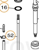
look that the parts breakdown, you will see the clip is down inside the lower unit keeping that shaft from coming out of the lower unit.
the 2 shafts are splined at the joint you have in the pic.
the reason you cannot see the splines is they are inside that joint
? simple to look at and see a male and female splined system at that joint.
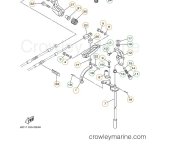
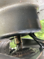
So your answer needs to be how to get those splined shafts apart? The coupling is brass. I know IF I was 100% sure it was splined with no clip I would make in my shop a mini tie rod or ball joint tool and drive that between those two parts, but how would you do it? Unless they already make that tool. These are more clips from the diagrams The first shows the only a spline on one end, the second show the shift rod #7 connected to the cam of sorts at top. Thats it, so you have had these apart before what are we seeing in the JPG above?
 

Attachments

  • F502B.JPG
    F502B.JPG
    34.1 KB · Views: 1
  • F50Shift.JPG
    F50Shift.JPG
    63.3 KB · Views: 1

99yam40

Fleet Admiral
Joined
Sep 7, 2008
Messages
9,095
16 is an o ring that goes on 14.
54 is the only c clip I see.
what makes you think the shift rod/linkage is what is keeping the lower unit from dropping as it should?

you telling the OP that he needs to undue the Shift shaft nut has taken this thread way off course
 

wmgeorge

Seaman
Joined
Jun 6, 2023
Messages
65
16 is an o ring that goes on 14.
54 is the only c clip I see.
what makes you think the shift rod/linkage is what is keeping the lower unit from dropping as it should?

you telling the OP that he needs to undue the Shift shaft nut has taken this thread way off course
I keep waiting for You to tell us here how you would fix? The first clip is showing only one end of that shaft is splined. The second clip shows one end of #7 is attached to the Cam and other may be that brass coupling. We have moved on from my F40 threaded coupling. So please tell us how you would fix this problem? If you don't know then maybe someone else can help.
 

99yam40

Fleet Admiral
Joined
Sep 7, 2008
Messages
9,095
if he really feels the SS is the problem cut it,
it is a small cost to replace compared to the drive shaft being cut and replaced.
at least I was not telling him to undue the nut on his SS that does not exist.
 

wmgeorge

Seaman
Joined
Jun 6, 2023
Messages
65
if he really feels the SS is the problem cut it,
it is a small cost to replace compared to the drive shaft being cut and replaced.
at least I was not telling him to undue the nut on his SS that does not exist.
Did you price check that shaft and is it available? Plus the time to replace? Did you even look? I would sure try to make that tool I described above and try that first.

As you might recall I told him to remove that cover and check to See if it had a coupling like mine.
 

99yam40

Fleet Admiral
Joined
Sep 7, 2008
Messages
9,095
ball joint/tie rod fork will not work, nothing for it to pry against.
you are the one that convinced him it was the shift shaft, even tho he did not have one like yours.
so you can now convince him that is not his problem
 

wmgeorge

Seaman
Joined
Jun 6, 2023
Messages
65
ball joint/tie rod fork will not work, nothing for it to pry against.
you are the one that convinced him it was the shift shaft, even tho he did not have one like yours.
so you can now convince him that is not his problem
You have never used A tie rod or ball joint separator have you ?
 

wmgeorge

Seaman
Joined
Jun 6, 2023
Messages
65
You have never used A tie rod or ball joint separator have you ?
And you could use something like a Claw hammer head, to separate the shaft from that brass coupling. I think a ripping hammer has a straighter claw. If it Must be cut do the brass coupling after finding the center.
 

wmgeorge

Seaman
Joined
Jun 6, 2023
Messages
65
And you could use something like a Claw hammer head, to separate the shaft from that brass coupling. I think a ripping hammer has a straighter claw. If it Must be cut do the brass coupling after finding the center.
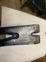
This is what I am thinking about, wrecking or pry bar, and a little work with a Dremel tool or angle grinder to make the V opening into the width of the opening between the brass coupling and the shaft as shown. Assuming there is no clip or other to be removed first.
 

Attachments

  • Bar.jpg
    Bar.jpg
    52.6 KB · Views: 1

wmgeorge

Seaman
Joined
Jun 6, 2023
Messages
65
This is what I am thinking about, wrecking or pry bar, and a little work with a Dremel tool or angle grinder to make the V opening into the width of the opening between the brass coupling and the shaft as shown. Assuming there is no clip or other to be removed first.
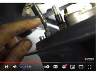
Something is a little off on the shift rod thing, two pictures captured off videos do not show the same as OP has posted. Is the Year and Model correct? A service manual would really, really help.
 

Attachments

  • ShaftJPG.JPG
    ShaftJPG.JPG
    55.7 KB · Views: 2
  • Shaft2.JPG
    Shaft2.JPG
    45.7 KB · Views: 2

wmgeorge

Seaman
Joined
Jun 6, 2023
Messages
65
Slow on the reply but I don’t see a nut on there just this
Is the picture above posted upside down? Rotated it makes sense, this is the rotated Picture..
 

Attachments

  • RotF50l.png
    RotF50l.png
    1 MB · Views: 2
Last edited:
Top