2003 Mercruiser 4.3 TB-V No Spark

TooBizzy

Cadet
Joined
Oct 23, 2009
Messages
20
I found a similar post that ended without a solution, so I copy and pasted the intitial post to save time in typing:

I have a 2003 merc 4.3L with thunderbolt V ignition
-I have 12 V at the + on the coil, it is within .3v of battery voltage. So very little wiring resistance
-I have 12 V at the red and white wire coming from the TB-V.
-I have disconnected the gray tac wire from the tach and verified the grey coil wire is not shorted
-I have disconnected both wires from the shift Int switch
-I have a gap light at the coil, no spark.
-If I take the green/white wire from the TB-V and tap it to a ground I get spark. This points to a bad ignition sensor.
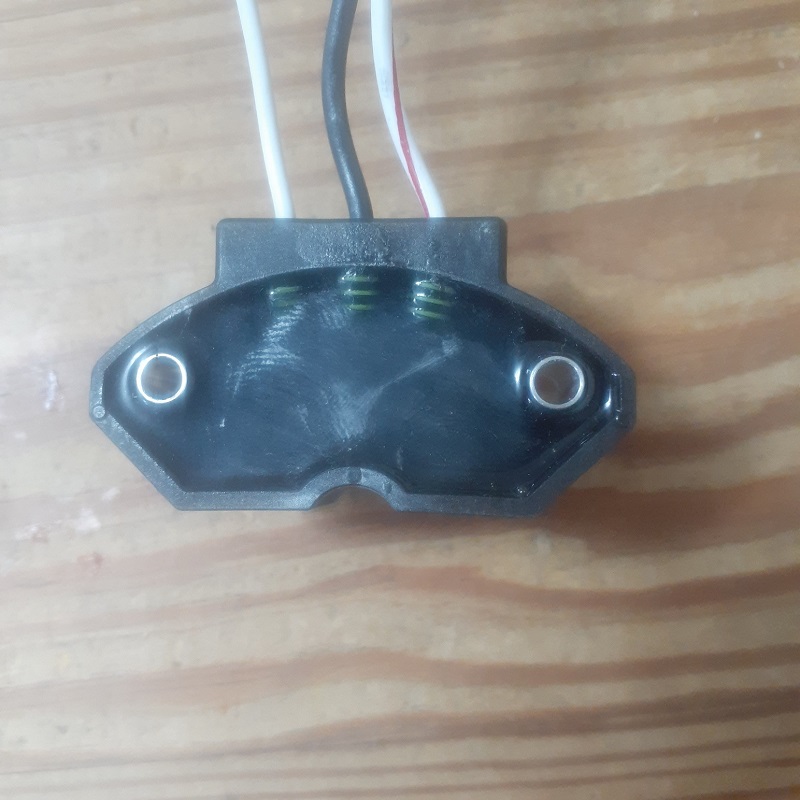
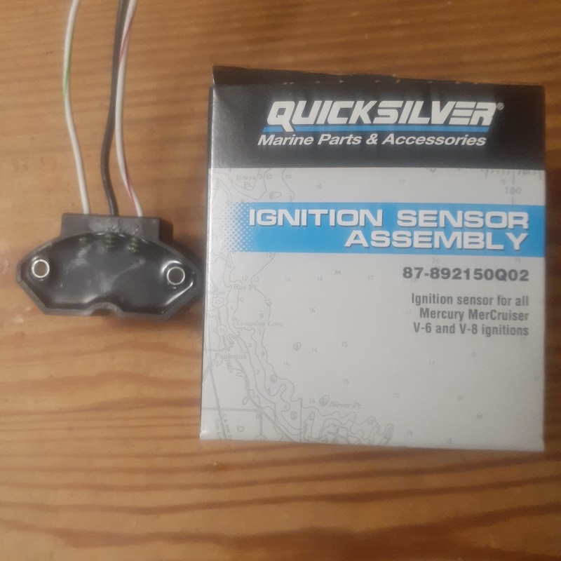
--Installed new cap, button, and Quicksilver (Mercruiser) Distributor sensor still no spark.
I then took a steel ruler and passed it though the sensor and old one (should go from 0v to 5v) but they didn’t. There is no voltage coming from the distributor grn/wht wire or any 0-5v pulse that the flow charts mention.
Can that mean another faulty sensor?? Even though I opted for the more expensive Quicksilver one??
I found another test in order to verify the module is working properly:
voltmeter red lead to wht/red lead coming from ignition module black meter lead to good ground, key on should see 12 (+) volts, with meter still attached hold the wht/grn wire from module to good ground and see if voltage drops momentarily then returns to 12 (+) volts - this will tell you the module is good and you need to replace the ignition sensor in the distributor
This test passed, it also produced a spark from the coil....

I also hooked up a wire to the - terminal of the coil with grey wire from the module still attached. Then struck it to ground. That produced a good spark from the coil? This indicates nothing is shorting out the signal side (-) of the coil. I'm out of ideas and can't find what the culpret can be. I've foloowed the flowchart for a TB-V to a tee and it still points to the dist sensor being faulty...What else can it be? I've got 2 after market sensors coming...Cheap $32.00 ...Last ditch effort before throwing an AC Delco Est or Pertronix in it! This is wearing me out! Have had this boat for about 12 years, always stored indoors and first electrical issue I've ever had with it.
 

TooBizzy

Cadet
Joined
Oct 23, 2009
Messages
20
Forgot to mention, I have 4.5v coming from the TB-V on the Grn/Wht wire. If the sensor is supposed to send a 0-5v signal to the TB-V throught the Grn/Wht wire , how is this supposed to work? Can anyone explain??
 

alldodge

Moderator
Staff member
Joined
Mar 8, 2009
Messages
41,223
Your saying you ran thru the TBV troubleshooting guide and you get spark wht/grn?

If correct did you install a new ignition sensor which had 3 wires and not the older 2 wire?
 

Scott06

Admiral
Joined
Apr 20, 2014
Messages
6,036
Your saying you ran thru the TBV troubleshooting guide and you get spark wht/grn?

If correct did you install a new ignition sensor which had 3 wires and not the older 2 wire?
And is the black wire off sensor on a clean ground
 

TooBizzy

Cadet
Joined
Oct 23, 2009
Messages
20
Yes and yes....Installed a brand new Mercruiser Quicksilver Dist sensor (with 3 wires), cap and button... I mounted the black grd wire off the sensor to the front of the engine block, verified block grd to ring on black terminal with ohm meter, no resistance...I tried mounting the sensor black wire to the harness black ground wire, same result. Also mentioned in OP that the red/wht wire off the TB-V and + side of the coil is 12.5v (key switch in run position) which is within .3v of actual (dual) battery voltage. So no resistance to speak of in any of the wiring. .3v drop is not that bad through all the connections and wiring harness to the start switch. Striking the grn/wht wire from the TB-V to ground produces a good spark between coil and cap with a spark gap tester, but can't get the new (or old sensor) sensor to output anything that would trigger the TB-V. I am getting no voltage out of the dist on the grn/wht wire during cranking or using a .030" thick piece of flat metal to break the magnetic field of the sensor. Also checked for any OHM difference on Wht/Grn from the dist to ground to see if there were any changes. It checks open or infinte during cranking and using the flat metal blade to break the magnetic field on the sensor. Absolutely no changes...I'm stumped as to what I am seeing. What are the odds of the $100 Merc sensor being bad out of the box? The ONLY thing I haven't done is back probe all the of the bullet connectors to see if there are any changes in voltage when plugging them in? I have used the extra bullet connectors and wires that came withthe new sensor to make checks a lot easier and haven't seen anything abnormal...
 

alldodge

Moderator
Staff member
Joined
Mar 8, 2009
Messages
41,223
Using a steel ruler and watching for a change IMO is not a good test. This is why in the troubleshooting guide it says the strike the Wht/Grn wire rapidly

The TBV is fairly simple, for me it's either the sensor or the distributor isn't turning
 

TooBizzy

Cadet
Joined
Oct 23, 2009
Messages
20
I have 2 more sensors coming, but opting for aftermarket so I'm not throwing lots more $$$ away with oem....The distributor shaft is turning, I had the same thought while troubleshooting this and pulled the cap to check! :)

Next step is to put a new sensor in and see if I get spark...If no spark, I'll go ahead and take distributor out and spin it by hand or with a drill...If Still no spark, I'll already have the distributor out for a new AC Delco!
 

Scott06

Admiral
Joined
Apr 20, 2014
Messages
6,036
Looks to be simple... but for me, so far Not So Simple! LOL
SO with new sensor installed you strike green/white wire from module to ground and you get a spark off the coil? Or you only tried this with the ruler? if yes to striking the wire with new module I would agree that yes the new oem sensor is bad and try the next new one and see.

Either way I think this points to the module being working so I would hold off on the Delco EST for the moment. IF you got a bad sensor they likely will replace it, as a spare doesnt hurt to have on the boat.
 

TooBizzy

Cadet
Joined
Oct 23, 2009
Messages
20
SO with new sensor installed you strike green/white wire from module to ground and you get a spark off the coil?
Yes...I get a spark from the coil even with the sensor wires unplugged when sticking the grn/wht wire to ground from the TB-V...When ordering the 2 aftermarket sensors ($32.00 for both) I was thinking the same. If it fixes my issue, I'll have a spare to put in the boat! Fingers crossed!
 

nola mike

Vice Admiral
Joined
Apr 22, 2009
Messages
5,237
Forgot to mention, I have 4.5v coming from the TB-V on the Grn/Wht wire. If the sensor is supposed to send a 0-5v signal to the TB-V throught the Grn/Wht wire , how is this supposed to work? Can anyone explain??
This is a 3 wire hall type "pull down" sensor. ICM uses a reference voltage, and there's a signal voltage through the sensor. When the signal wire is grounded to the ICM, it thinks the switch is closed (signal voltage is pulled down from 5v-->0)

I mounted the black grd wire off the sensor to the front of the engine block, verified block grd to ring on black terminal with ohm meter, no resistance...I tried mounting the sensor black wire to the harness black ground wire, same result.
Can't quite picture this, but the sensor ground may need to be grounded through the ICM. Check your ground coming from ICM-->block

Also mentioned in OP that the red/wht wire off the TB-V and + side of the coil is 12.5v
Good
Striking the grn/wht wire from the TB-V to ground produces a good spark between coil and cap with a spark gap tester,
Your ICM is good

but can't get the new (or old sensor) sensor to output anything that would trigger the TB-V. I am getting no voltage out of the dist on the grn/wht wire during cranking or using a .030" thick piece of flat metal to break the magnetic field of the sensor.
This is with everything connected? If the grn/wht is disconnected, you'll get either a steady 0v or 5v from the sensor grn/wht no matter what, and 5v from the ICM

Also checked for any OHM difference on Wht/Grn from the dist to ground to see if there were any changes. It checks open or infinte during cranking and using the flat metal blade to break the magnetic field on the sensor.
Again, not valid with a disconnected wire.
With everything connected, back probe the grn/wht and black wires. Should get 5v. With metal in front of the sensor, that should drop to 0v.
 

TooBizzy

Cadet
Joined
Oct 23, 2009
Messages
20
Can't quite picture this, but the sensor ground may need to be grounded through the ICM. Check your ground coming from ICM-->block
I haven't checked the ground wire from the ICM to the block but will make this check...I was basically checking the black grd wire from the sensor (as connected to block) to other places on the block and it shows no resistance.Double checking ICM ground to block ground will verify there is no issue.
Again, not valid with a disconnected wire.
With everything connected, back probe the grn/wht and black wires. Should get 5v. With metal in front of the sensor, that should drop to 0v.
I have not done this either. But makes sense. Hoping I find something, I'm getting an itchy finger for the "Buy it now" button for the Ac Delco system! But really would like to figure this out and keep what I have. I've owned this tri-toon for about 15 years now and it's pretty much been trouble free. Thank you for taking the time to explain in greater detail. I appreciate it!
 

TooBizzy

Cadet
Joined
Oct 23, 2009
Messages
20
So....Got the new Ebay cheap sensors ($16.00ea) yesterday and had a chance to work on it today. A few days ago I back probed every connection for grounds and voltages...The grn/wht wire showed 4.5v even putting metal between the sensor, it would not drop to 0 volts....All connections tested good for grounds and voltages...

Today I put one of the new cheap sensors in and it fired right up!! My only concern now is how long will a Cheap one last?!

Looking at the New OEM Quicksilver sensor, it appears there are tiny springs on the bottom side not completely covered with epoxy or whatevery they use connected to the input/ouput wires...I am speculating that the sensor shorted when I first installed it and damaged it since I couldn't get it to fire...Who knows, just a guess. See photos...I'll take it back and see if I can get a new one? They might be a little finicky on electronic returns/exchanges?

So many times people don't follow up with a solution and leave you hanging when doing searches on forums. I am very grateful for the responses that kept me heading in the right direction, even though the flow chart was telling me the "New OEM Quicksilver" dist sensor was faulty....Just wasn't making sense that a brand new OEM $110 part could be bad! Hoping this response helps others with the same issue!

OH and BTW, as other reviews on these cheap sensors have commented, the hole pattern doesn't quite line up with the holes in the dist making it impossible to get the screws started....Even taking off the foam pad on the front of the sensor....The holes in the aluminum bushings in the sensor were tapered about .010" and was just enough that no way was it going to line up. I took a .213" drill and straightened out both holes which allowed the holes to line up.

Again thanks for all the help!

sensor_1.jpg


sensor_2.jpg
 

alldodge

Moderator
Staff member
Joined
Mar 8, 2009
Messages
41,223
Might mention it to Merc Tech support

Was the sensor bought from a major seller of Merc parts or Amazon sell everything kind of place?

And many thanks for the update
 

TooBizzy

Cadet
Joined
Oct 23, 2009
Messages
20
I purchased it at a Mercruiser Dealership close to where I live. They had it in stock.
 
Top