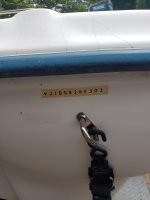
Travis Boat Sales on Highway 35E in Lewisville, Tx. used to sell them. I had one, as a matter of fact, was the second owner, 2 year old boat, 2002 edition..... my Avatar is it with a 90 Merc....kissing 50. It was aluminum Bass Boat, had a stepped hull so at the time the picture was taken, trying to drive and focus my cell phone, only the center 15" give or take of the hull were getting wet...like a FG bass boat "pad" but crimp-steps, not smooth flowing lines like is done with FG. It was a 17 1/2 feet, Travis Edition. I think it sat on a Fish Master trailer. I assumed that the boat company made up these boats especially for the Travis boat sales folks. The boats were made in Arkansas and I don't think they are still making boats.
Mine had the Merc Commander 3000 remote control and the key number was a number and letter. I changed to a Commander 2000 as I liked the fast idle function better and it came with the same type of Merc. number-letter key. I currently have a 2002 115 Merc out in the garage and it has one of the Merc keys. There are only about 2 or 3 number letter combinations.
If Merc, switch is color coded wires coming out the back of a plastic molded assembly...unrepairable, which wind up as a pin number at the other end of the wiring harness where it connects to the engine internal wiring harness.
So I'll give you the wiring harness connector pin number, wire color code, and function:
1. Black wire yellow stripe: Fuel enrichment (choke)....sends 12v to the fuel enrichment solenoid which, when the fuel primer bulb is firm, squirts fuel directly into the intake manifold when the key is turned to the ON (1st click CW) position and the key is pushed in...depressed into the rear of the control box about 1/4".
2. Purple or Red with Purple stripe: Switched 12v from the battery through the ignition switch in the ON or START positions for whatever usage is needed for switched 12v.
3. Tan with light Blue stripe is the over temp or low oil in the oil reservoir warning function. Ground comes from the engine under a fail condition and applies ground to a failure warning horn either in the control or mounted externally to the wiring bundle at the control or under the dash locations. Some boats also have a dash mounted visual indicator too. Power to the othe side of the horn is switched 12v.
4. Black is ground/battery neg. When the iginition switch is in the off position it sends ground to the triggers to the engine on the yellow wire/black stripe wire at the connector Pin 6.
5. Grey wire is the tach signal from the engine to a dash indicator. It had nothing to do with the ignition switch.
6. As mentioned in Pin 4 verbiage, the yellow wire with black stripe is connected to the trigger circuits/modules in the engine and when the ignition switch is in the OFF position, grounds that wire, killing triggers and stopping the engine.
7. Red wire with yellow stripe: In the START position the switch sends battery voltage to the starting solenoid energizing coil closing the high current circuit and spinning the starter as long as the spring loaded key is held in the START position.
8. The center pin is Red and battery voltage...12 v respectively. It is routed through the switch as described above.


