1995 force 70 hp ignition help

Woodstock60

Petty Officer 1st Class
Joined
Dec 14, 2008
Messages
238
I know their is a section on this in here, but my head is spinning with numbers and I'm not very good with electric testing, and I have a 5 day fishing trip coming up in 2 weeks and I'm panicked.
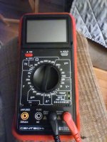
My problem is on this motor, suddenly no spark at all on all 3 cyl. , thought it was the stator, bought a new one , put in in carefully still no spark. Decided to test all ignition components, and I just don't know how to use one of these meters, and I can't figure out what the specs should be any way, I desperately need someone to walk me through it like I am ab6 year old. What I have been able to do is eliminate the stator and the kill switch. I need to test the trigger, the regulator \ rectifier, switch box. Thanks to anyone that can teach me. I also need to be shown what settings my meter needs to be set on, the ohms area has 7 different settings
 

Attachments

  • IMG_20230823_193357.jpg
    IMG_20230823_193357.jpg
    1.3 MB · Views: 6

brodmann

Chief Petty Officer
Joined
Jun 17, 2008
Messages
426
I'm sure you can find the specs for your motor and the testing procedures for each one of those items online As fas as reading resistance in ohms, your setting will depend on what you're looking for. If the spec says your reading should be between 1 and 6, put the setting on a low setting. If your spec says that the item you're testing should give a result between 650 and 900, set the meter on 1000, or 1K. An ohm shows the resistance to electrical of an item. The resistance in a spark plug wire will be very low. It's a large wire designed to carry very high voltage. On every boat i've ever owned the kill switch is easy to test. There's a wire that comes from the ignition system that goes to the kill switch and another wire that goes to a ground. When the kill switch (lanyard style) is in tact, there is complete resistance between the two wires, because you do not want to ground your ignition system. If you pull that little clip out, it makes contact between the two wires to ground your ignition system, so the resistance will show "0". When you turn your key switch "OFF", all it does is ground the ignition system. First, check your ignition switch. With the key in the "on" position, you should have 12v between the red wire and the black/yellow wire on the back of the switch. That's what powers the ignition system. If that checks out, the next thing i do is remove the black wire from the ignition switch and try starting the motor. The black wire grounds the ignition system when you turn the key off. If the motor starts with the black wire off, you have a simpe wiring issue. Either inside the switch or in the black wire somewhere. Let me know what you find. On your meter, it should indicate either AC voltage and DC voltage. If not, the DC voltage setting is sometimes used to test small batteries that produce 1.5 volts, so the DC testing scale will probably have a setting of "2" on the dial. The AC scale should only have higher settings like 120, 240 and possibly a couple of others.
let me know how that goes.
 

Nordin

Commander
Joined
Jun 12, 2010
Messages
2,555
Follow brodmann is a good starting point, BUT NO NO NO 12V AC or DC at the kill switch.
This engine has CDI ignition system and there should not be any voltage at the kill switch, if there is the CDI box is bad.
Checking resistance (Ohm) at the components gives you some information but to be really sure about the status of the components you need to check the voltage output from them.
Outboardignitiondotcom has the troubleshoot chart and the specs.
General specs.
Triggers 48-52hm
Stator 450-600 Ohm (OEM)
CDI box Can not be checked by resistance.
 

Woodstock60

Petty Officer 1st Class
Joined
Dec 14, 2008
Messages
238
So there is no regular kill switch on this boat, where you would pull out a clip and the engine would ground. But the key switch would stop the engine in the off position. Is there a way I could have pulled a wire to it that would allow me to crank the engine, but it would still not let power to the ignition?
I was moving things around under the key switch prior to the spark cutting out. Just one more thought in my head.
You talk about checking resistance and voltage, these are the things I need to be walked through. In my original post I put a picture of my meter, can anyone point out what setting to put it on when checking each individual thing?
 

Nordin

Commander
Joined
Jun 12, 2010
Messages
2,555
You can check the output voltage with your VOM, BUT the best is to have a DVA meter or a DVA adapter to your meter.
The DVA adapters purpose is to store the peak voltage output so you are able to se the value of it.
You can use your meter but you would not been able to se the actual peak voltage.
The stator for charging the capacitor in the CDI box would put out 200+VAC.
The triggers would put out 0,5+VAC.
 

Woodstock60

Petty Officer 1st Class
Joined
Dec 14, 2008
Messages
238
You can check the output voltage with your VOM, BUT the best is to have a DVA meter or a DVA adapter to your meter.
The DVA adapters purpose is to store the peak voltage output so you are able to se the value of it.
You can use your meter but you would not been able to se the actual peak voltage.
The stator for charging the capacitor in the CDI box would put out 200+VAC.
The triggers would put out 0,5+VAC.
It says dc 1000v, AC 700v
 

Nordin

Commander
Joined
Jun 12, 2010
Messages
2,555
That are some of the ranges at your VOM, right?
As you do not have a DVA adapter you have to set the VOM at 700V AC when measure the stator cause the stator output is AC voltage.
When measure the triggers output set the VOM at 2V AC.
If you use a DVA adapter to your VOM you have to set the VOM at DC ranges cause the DVA adapter rectifier the output AC voltage to DC voltage.
Hopefully you will notice the peak voltage when cranking with the starter.
 

Woodstock60

Petty Officer 1st Class
Joined
Dec 14, 2008
Messages
238
Well thanks for trying to help me, but I just don't have the time to try and learn how to do these tests. They may seem simple to Some, but not me, so for the benefit of others I broke the rule and just started throwing parts at it and got lucky, first a new stator, no spark, then rectifier, no spark, checked the trigger visibly looked good, found an aftermarket switch box ( powerpack) for cheap money, bingo. Upon inspecting the old one it was bulging and cracked in the back, the side bolted to the panel so it wasn't easy to see. ThankS to the guys who tried to help me
 

topgun3690

Lieutenant Junior Grade
Joined
May 7, 2019
Messages
1,034
I broke the rule and just started throwing parts at it and got lucky, first a new stator, no spark, then rectifier, no spark, checked the trigger visibly looked good, found an aftermarket switch box ( powerpack) for cheap money, bingo.
Well at least it was YOU who pulled the trigger on the "Parts Cannon" and not some shady repair shop trying to get in your wallet......you fixed the problem yourself and now have a new ignition system.....trouble-shooting is the preferred method but sometimes you get lucky throwing parts at it......as long as you are happy with it, it's all good. (y)
 

jerryjerry05

Supreme Mariner
Joined
May 7, 2008
Messages
18,040
Sometimes checking/testing can't find the problem.
Tested a stator 3 times, tested good 3 times. Nope,it was bad.
 

brodmann

Chief Petty Officer
Joined
Jun 17, 2008
Messages
426
Your meter is much more sophisticated than what you need as a beginner. The Omega (horse shoe symbol at the top) is for testing ohms (resistance), the straight line with dashes underneath is for testing DC voltage. That's battery current. The squiggly line is for testing AC current, like what's in your house. I can't think of any reason for you to use more than those three items on that meter. I'm sorry if I've over-simplified thing, I'm not questioning your intelligence, just explaining is the most basic terms.
 
Top