1995 4.3 liter mercruiser

kmad1999

Recruit
Joined
Jul 21, 2022
Messages
3
Anyone got this engine in a lund? Mine is an 1850 Signature Tyee but I'm sure any mid 90"s lund with this engine will be similar. I started an engine rebuild last fall and took a bunch of pictures on my tablet before I tore down the top end. I did so to show where all engine lift brackets went plus the odd mounting bolt locations on the intake manifold and valve covers. Odd as in bolts with stud ends for mounting other equipment or spark plug wire brackets. Also had pictures of wiring location. The problem is my tablet was stolen and I have no idea were some of this stuff goes. An exploded view in a manual is just and illustration and does not show bolt differences. I need some pics of intake manifold mounting bolts (12 bolt manifold) and valve cover mounting bolts to start or if anyone has a suggestion as to were I can get the information. Thanks in advance.
 

Bondo

Moderator
Staff member
Joined
Apr 17, 2002
Messages
70,958
Odd as in bolts with stud ends for mounting other equipment or spark plug wire brackets

Ayuh,..... Welcome Aboard,..... I've got a '94 sittin' on my shop floor right now,....
The 3/8"-16 odd bolts, go in the upper 2 bolt holes holdin' the flywheel cover to the block flange,....
That's where battery ground, 'n the plug wire legs go,....

The valve covers don't use any odd bolts,....

'n on the intake, I'll have to look tomorrow,....
 

Rick Stephens

Admiral
Joined
Aug 13, 2013
Messages
6,118
Anyone got this engine in a lund? Mine is an 1850 Signature Tyee but I'm sure any mid 90"s lund with this engine will be similar.
FYI, boat model is irrelevant. For the most part that model 4.3L motor will be the same in everyone's boat.
 

kmad1999

Recruit
Joined
Jul 21, 2022
Messages
3
Ayuh,..... Welcome Aboard,..... I've got a '94 sittin' on my shop floor right now,....
The 3/8"-16 odd bolts, go in the upper 2 bolt holes holdin' the flywheel cover to the block flange,....
That's where battery ground, 'n the plug wire legs go,....

The valve covers don't use any odd bolts,....

'n on the intake, I'll have to look tomorrow,....
OMG... thanks. I'll apologize in advance because I'm probably going to bug the hell out of you. There seem to be 4 of the odd bolts with the post on the end in my set of 12 intake manifold bolts.
 

Scott06

Admiral
Joined
Apr 20, 2014
Messages
6,451
OMG... thanks. I'll apologize in advance because I'm probably going to bug the hell out of you. There seem to be 4 of the odd bolts with the post on the end in my set of 12 intake manifold bolts.
The other two studs probably go on the starboard front engine mount. Two of the three fasteners on mine were studs to mount the fuel filter bracket
 

Bondo

Moderator
Staff member
Joined
Apr 17, 2002
Messages
70,958
OMG... thanks. I'll apologize in advance because I'm probably going to bug the hell out of you. There seem to be 4 of the odd bolts with the post on the end in my set of 12 intake manifold bolts.
Ayuh,.... What I found on my motor is,.....
The 2 front bolts are the odd bolts, with nothin' on 'em,....
'n aft starboard side is 2 more, with the liftin' ring, under the bolt heads,.....
the very back one has the cannon plug bracket on it with a nut, the other one is empty,....
 

kmad1999

Recruit
Joined
Jul 21, 2022
Messages
3
The other two studs probably go on the starboard front engine mount. Two of the three fasteners on mine were studs to mount the fuel filter bracket
Haven't had much time to work on it. Too many other irons in the fire. Any reason why my 16413-C1 thermostat housing would not have had the check ball assembly in it?
 

Scott06

Admiral
Joined
Apr 20, 2014
Messages
6,451
Haven't had much time to work on it. Too many other irons in the fire. Any reason why my 16413-C1 thermostat housing would not have had the check ball assembly in it?
Someone didn't know WTF they were doing would be my guess.

Do you have separate cooling hoses feeding both the manifolds and elbows? if so you need the check balls. If you have just two hoses feeding the exhaust manifolds only (passes water up through elbows constantly even when thermostat is closed) I dont think there will be check balls
 

havoc_squad

Senior Chief Petty Officer
Joined
Mar 5, 2011
Messages
738
To the op, I'm curious what your boat hull supports look like for how it secures the front motor mounts.

As part of your engine rebuild project, could you post some pictures of how the front motor mounts are supported/reinforced?

There isn't much documentation of what works best in a suitably sized aluminum boat to replace the front engine mounts of an inline 4/6 with a 1992 or later GM 4.3L V6 for alpha one gen 2 setups.

It's obvious what fiberglass boat manufacturers usually do but forum searches and internet photos come up empty for aluminum boats.

My best guess from what I've seen in hard to tell photos is some thick angle/square aluminum is ran all the way from the transom to the front v6 engine mounts.
 

Scott06

Admiral
Joined
Apr 20, 2014
Messages
6,451
To the op, I'm curious what your boat hull supports look like for how it secures the front motor mounts.

As part of your engine rebuild project, could you post some pictures of how the front motor mounts are supported/reinforced?

There isn't much documentation of what works best in a suitably sized aluminum boat to replace the front engine mounts of an inline 4/6 with a 1992 or later GM 4.3L V6 for alpha one gen 2 setups.

It's obvious what fiberglass boat manufacturers usually do but forum searches and internet photos come up empty for aluminum boats.

My best guess from what I've seen in hard to tell photos is some thick angle/square aluminum is ran all the way from the transom to the front v6 engine mounts.
Aluminum boats typically have wood blocks screwed to stringers or aluminum angle bolted to them. Look at starcraft restos on here for more details

@Bondo likely has some experience
 

havoc_squad

Senior Chief Petty Officer
Joined
Mar 5, 2011
Messages
738
Aluminum boats typically have wood blocks screwed to stringers or aluminum angle bolted to them. Look at starcraft restos on here for more details

@Bondo likely has some experience

Bondo a few hours ago gave me a direct response on what he directly did on his own 3.0L inline 4 to GM V6 conversion. No photos but it was at least a good starting point.

The big issue was I couldn't find any photos in my iboats forum search and the internet of aluminum I/O boat v6 equipped engine with engine removed to see the front engine mounting system in detail.

After Bondo's description and some photos of some empty engine bays of some aluminum I/O boats with Inline 4/6 engines, some ideas begin to form.
 

Rick Stephens

Admiral
Joined
Aug 13, 2013
Messages
6,118
You will need a couple things to get a starting point, which is locating the new mounts. Merc doesn't have installation drawings before 1996 any longer, but I think I can attach that here for your motor.

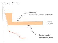
Next is building a simple jig that you can hold to your transom plate and determine mount height. For this jig you clamp an angle iron to the top of the rear motor mounts on the transom plate and slide the top flat of the jig up under that. The lower edge is front mount height. There are three dimensions that determine mount height - transom angle to motor is ALWAYS 13º. Front mounts are always 4" below rear mounts on that 13º angle. Hence the jig.

jig.jpg
 

Attachments

  • 4.3 dimensions.pdf
    191.4 KB · Views: 1
Top