1993 5.0 Cobra EFI Alternator/Electrical Question

Bsluper

Cadet
Joined
Jul 5, 2019
Messages
27
This entire community has been incredible and my boat has never been in better shape thanks to you all! I do have 1 last issue that I could use some help with. My alternator seems to only be putting out 11 1/2 volts. I have 2 new batteries, had the alternator checked out and it was putting out 14+ volts on a test bench at an alternator repair shop. I checked the output and got the 11 1/2 volt reading directly at the back of the alternator once it was reinstalled. In addition I check the purple wire from the ignition to the alternator which showed .9 ohms and about 11 1/2 volts as well. I don't know a lot about this type of stuff and could really use some help! THANK YOU in advance for any and all advice!!!!!!
 

alldodge

Moderator
Staff member
Joined
Mar 8, 2009
Messages
42,346
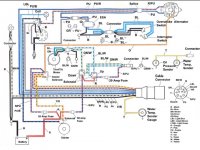
Think you might be missing a connection or your not getting power to the Red/Purple wire. Note the splice

OMC Engine Wiring.jpg
 

Bsluper

Cadet
Joined
Jul 5, 2019
Messages
27
Think you might be missing a connection or your not getting power to the Red/Purple wire. Note the splice

View attachment 340422

I appreciate your assistance and providing a wiring diagram. Unfortunately I have Ford 5.0 EFI, not the GMC. The 3 color cables I have at the alternator are Purple (EXC) Black (Ground) and Orange. The steps I have taken so far are to check the purple cable which is doing 12 volts from the ignition switch to back of alternator. Check the orange cable which is only outputting 11.5 volts to the batteries and also I was instructed to run a cable from black of the battery to ground on the alternator to see if the boat had a faulty ground, but that did not effect anything. Any next steps or advice would be GREATLY welcomed and appreciated!!!!!
 

Bsluper

Cadet
Joined
Jul 5, 2019
Messages
27
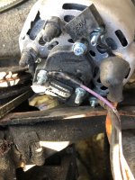
Also, I have included a photo of the back of my alternator for reference!
 

Attachments

  • IMG_4623.jpg
    IMG_4623.jpg
    2.3 MB · Views: 11

alldodge

Moderator
Staff member
Joined
Mar 8, 2009
Messages
42,346
Unfortunately I have Ford 5.0 EFI, not the GMC

As with all questions posted its best to let us know what ya got

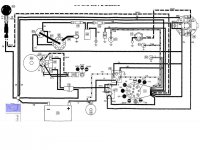
Here is the Ford and note the jumper on the ALT

Ford 50_58 wiring.JPG
 

Bsluper

Cadet
Joined
Jul 5, 2019
Messages
27
As with all questions posted its best to let us know what ya got

Here is the Ford and note the jumper on the ALT

View attachment 340430
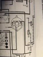
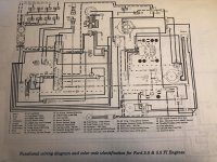
Sorry, I didn't know that any of the GMCs had EFI like I stated in the title, but we're almost there! I have the Ford 5.0 with Electronic Fuel Injection. Specifically Model # 50FAPRJVN. I don't have a digital copy but I have a b/w paper copy of the diagram (Page A-45, not A-44) from the SELOC manual (Atleast I think that's the correct diagram). Thanks again for any and all advice that you can provide!
 

alldodge

Moderator
Staff member
Joined
Mar 8, 2009
Messages
42,346
Sorry, I'm old, not well versed with OMC linage, and missed the efi. So if ya make it easy on me it won't take as long, otherwise your requiring me to do research to make sure I have what someone is look for. If I would have seen 50FAPRJVN it would have come out different on first post

My bad, have a good evening
 

Bsluper

Cadet
Joined
Jul 5, 2019
Messages
27
Sorry, I'm old, not well versed with OMC linage, and missed the efi. So if ya make it easy on me it won't take as long, otherwise your requiring me to do research to make sure I have what someone is look for. If I would have seen 50FAPRJVN it would have come out different on first post

My bad, have a good evening
No worries at all, I hope I didn’t come across rude, that wasn’t my intent. If you have any ideas on what the problem could be I’d still love to hear!
 

Bsluper

Cadet
Joined
Jul 5, 2019
Messages
27
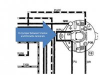
Put a jumper between S and EX
View attachment 340449
I love the 5am response! I took a photo of my wiring diagram so that we are on the same page about mine being the Ford 5.0 Electronic Fuel Injection. With that being said, if I put a jumper between the S-sense and Ex-Excite terminals can that damage anything? Just worried since the wiring diagram for my engine shows no jumper there. Also, I still haven't said this enough, THANK YOU! This has been plaguing me for years and I just don't know enough about the electrical stuff to fix it without some guidance.
 

Attachments

  • IMG_4742.jpg
    IMG_4742.jpg
    1.4 MB · Views: 10
  • IMG_4743.jpg
    IMG_4743.jpg
    2.4 MB · Views: 11

alldodge

Moderator
Staff member
Joined
Mar 8, 2009
Messages
42,346
My diagram is from a Ford 5.0 and 5.8
All (GM, FORD, Idmar , etc) ALT's except one wire ALT's use both a Sence and a Excite lead. The one wire types have both connections made internally.

Don't know about your diagram so I'm unsure if it was left off because it was missed or something else like not showing anything but the main connections.
 

Bsluper

Cadet
Joined
Jul 5, 2019
Messages
27
Bump/New information: So I operated completely off Battery 1 on Saturday, ran the boat for 90-120 mins, turned on and off 5 or 6 times no issues. Voltage on the battery before I started the day was 12.65, voltage when I ended the day was 12.45 and at no point in time did the alternator gauge go above 11 1/2 volts. Any ideas from anyone would be awesome!
 

Bsluper

Cadet
Joined
Jul 5, 2019
Messages
27
My diagram is from a Ford 5.0 and 5.8
All (GM, FORD, Idmar , etc) ALT's except one wire ALT's use both a Sence and a Excite lead. The one wire types have both connections made internally.

Don't know about your diagram so I'm unsure if it was left off because it was missed or something else like not showing anything but the main connections.
@alldodge so I did some research and I have a 3 wire alternator. The diagram that you keep referencing is for a Ford 5.0 with carburetors, mine is a bit difference with electronic fuel injection, I don't have carbs. Don't get me wrong, I'm hugely appreciative and I can tell that you know more about this than I do, so I'm still very open to feedback, suggestions and advice!
 

alldodge

Moderator
Staff member
Joined
Mar 8, 2009
Messages
42,346
I don't have a diagram from your motor. I have one for the 5.8 (351) MPI and it also shows a jumper between the two points. Not saying yours is this way, but may be spliced inside the harness.

Measure voltage on each wire with key on and off to see if either or both switch
 

Lou C

Supreme Mariner
Joined
Nov 10, 2002
Messages
12,815
These older OMCs had some quirks in the wiring harness. I had 2 in mine:
The alt had the separate excite & sense terminals.
Issues: while volt meter indicated typical readings the voltage at certain rpms surged up and down. Eventually replaced the alt with an ARCO and learned from ARCO marine that:
The OMC sense wiring circuit can have high resistance and this can results in battery overcharging, yet the dash gauge does not show that. The instructions that came with the new alt said to check charging voltage at the batteries. When I did this I got 15.5v so it was definitely over charging. Their solution was to disconnect the sense lead at the alt, tape it up in the harness and run a jumper from the B+ terminal to the S terminal. After doing this my batteries were right at 14.2v, but my dash voltmeter read lower 11.5-12v. I assumed that this was high resistance in the dash wiring but I later found out that was not the cause.
I checked battery volts at the ignition switch and it was good, 12.6. However when the ignition was turned on it dropped to about 11.5v. So the dash gauge was actually correct! To see where the problem was I got some heavy gauge wire and added a supplemental ground from the fuse box to the batt -. No change. Then did the same with the positive. Voltage normal. So I thought the wiring on the positive side was undersized for the loads. I ran a supplemental power lead (8 gauge wire fused) from the battery switch common to the fuse box positive terminal. Now, voltage at the ignition terminal and at the voltmeter were normal. I’m not saying this is the “right” way to fix this but it has worked fine for about 4 years now. With the engine running my voltmeter reads 14v.
Not sure if any of this has any relevance to the OP’s issue.....
 
Top