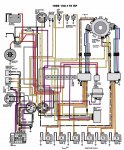
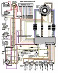
1990 evinrude 200hp v6 power pack wiring

hunter200v6

Recruit
Joined
Jul 18, 2017
Messages
1
I recently picked up my boat from a mechanic who had it for around 6 months (was originally supposed to be a 2 week job). I got tired of waiting on him. He replaced the power pack to fix the ignition issue with my boat but that did not work so he instead suggested that the problem was the timer base. Upon getting the boat back in my garage I replaced the timer base myself with a CDI version. However, when putting everything back together I learned that my mechanic did not finish connecting all the wires that go to and from the power pack and he apparently still has the bolts which hold the power pack in place in his possession. I'm pretty sure I can locate the correct bolts to replace the ones that are missing so that's not really an issue. However, I have spent hours upon hours scouring the internet in search of a detailed wiring diagram to correctly wire my power pack back in. I feel pretty confident that I have most all of the wires properly connected based on the vague diagrams that I've found on the web and just due to the fact that they're color coded. I don't want to run the risk of firing up my motor to adjust the timing, since I installed the new timer base, and something going wrong. Any assistance, more detailed wiring diagrams would be greatly appreciated!

1990 evinrude v6 200hp
 

jbuote

Lieutenant Junior Grade
Joined
Aug 17, 2016
Messages
1,001
Not sure, but this is out of a 1973 - 1991 manual for 60 - 235HP Johnson/Evinrudes...
Does this help you at all?

90 200hp Wiring.pdf
 

Attachments

  • 90 200hp Wiring.pdf
    864.1 KB · Views: 79

daselbee

Commander
Joined
Jan 20, 2009
Messages
2,765
It is color coded as you state. Match up the proper sex of the connectors and the color, and it is done.
The only one that is weird is the black/yellow wire coming from the shift interrupt switch. If you wire it wrong, it wont blow anything up, but will exhibit
strange failures like not able to shut off, or three cyls not firing....just weird stuff.
Be sure to attach the black ground to the stbd rear stud before trying to run it.
 

cfauvel

Chief Petty Officer
Joined
Aug 16, 2005
Messages
645
does this motor have one or two powerpacks? the primary leads (orange in color) have a stripe...
mine has two and the colors are as follows
Orange/blue - top cyl
orange - mid cyll
orange/green - bottom cyl

these are not exactly for your engine...but....they might help if yours matches one of them 1986_150_175_wiring.jpg
1988_89_200_225_wiring.jpg


UPDATE: MLA Bibliography format

[FONT=&quot]"1986 150 Thru 175 Wiring Diagram." [/FONT]1986 150 Thru 175 Wiring Diagram[FONT=&quot]. N.p., n.d. Web. 19 July 2017. <http://www.maxrules.com/graphics/omc/wiring/1986_150_175.jpg>.

"1988 - 1989 200 Thru 225 Wiring Diagram."
[/FONT]
1988 - 1989 200 Thru 225 Wiring Diagram[FONT=&quot]. N.p., n.d. Web. 19 July 2017. <http://www.maxrules.com/graphics/omc/wiring/1988_89_200_225.jpg>.[/FONT]
 
Last edited:

daselbee

Commander
Joined
Jan 20, 2009
Messages
2,765
^^^^^^ This is why Clymer is generally considered to be a poor service manual.
The diagrams are straight out of a Clymer,
and,
Error #1....color depicted for Cyl #1 primary wire is wrong. It is orange/blue, that drawing is showing blue/orange. Just look at diagram for the dual powerpack model above.
Error #2....On the left side, various components are shown. The words "cut off switch" have a drawing directly below the word "switch". There is no such component on this engine. The drawing doesn't even attempt to identify the component.

You have to be careful with Clymer, they have some useful information, but only if you know what to disregard as an error......
 

oldboat1

Fleet Admiral
Joined
Apr 3, 2002
Messages
9,598
^^^add that they are lifted without attribution. Copyright issues aside, technical info. needs to be sourced for reasons suggested above. Some instructions are suspect for technical reasons.
 

cfauvel

Chief Petty Officer
Joined
Aug 16, 2005
Messages
645
My source was as follows Sticky_for_stuff.png


Just trying to help the guy...
 
Last edited:

jbuote

Lieutenant Junior Grade
Joined
Aug 17, 2016
Messages
1,001
And in the interest of full disclosure, the pdf I provided was a saved page I have from:

http://boatinfo.no/lib/evinrude/manuals/1973-1991johnsonevinrude.html#/404

​Admittedly, I've heard good and bad about that site.. I know the wiring diagram for my engine that I got from there is spot on..
Maybe this diagram is or isn't right.. I don't know.. Just offered it up as a possible source for the OP to decide to use or not..

​I suppose I should have pointed to the source I got it from in the first place, but was just trying to help.. :)
 

daselbee

Commander
Joined
Jan 20, 2009
Messages
2,765
I know Chris....I just wanted to show in a real time example those interested that Clymer is often in error. That's all.
If he knows the engine, and can cherry pick out the errors, then I guess Clymer can be useful.

But sure, I do understand your intentions....


AND, case in point......I stated that the second error was that weird looking drawing directly below the word "switch".....well looking again, I see
that it COULD BE either the in tank oil low sender switch OR the fuel vacuum switch for fuel restriction alarm. It is not identified.
 

cfauvel

Chief Petty Officer
Joined
Aug 16, 2005
Messages
645
I know Chris....I just wanted to show in a real time example those interested that Clymer is often in error. That's all.
If he knows the engine, and can cherry pick out the errors, then I guess Clymer can be useful.

But sure, I do understand your intentions....


AND, case in point......I stated that the second error was that weird looking drawing directly below the word "switch".....well looking again, I see
that it COULD BE either the in tank oil low sender switch OR the fuel vacuum switch for fuel restriction alarm. It is not identified.


the one powerpack diagram (88-89 225) ....do you think that they were trying to differentiate the left side and right side leads?
I think they got the color wrong on the kill circuit they have it as yellow/black.....that should be black/yellow...
 

daselbee

Commander
Joined
Jan 20, 2009
Messages
2,765
No I think they just got it wrong, period. Look at diagram for two PP motor...they got the colors right there.
I looked at the posted boatinfo.no drawing, and I see they are calling out orange/black for #1 and #2 primary wires. That is wrong...it is orange/blue.

And very good eye!!! Yellow/black is NOT correct. Black/yellow always.....
 

daselbee

Commander
Joined
Jan 20, 2009
Messages
2,765
Here is another HUGE mistake. This one is monumental....

The Yellow and Yellow/Gray pair coming from the stator does NOT go to the powerpack. That drawing shows the pair going to the pack.

That yellow pair goes to the water cooled reg/rectifier which is not even on the diagram.

It looks as if they "bundled" the powerpack diagram and the reg/rect into one rectangular drawing. Should be two separate illustrations.

Now if you didn't know better, wouldn't that just confuse the he'll out of you?
 

daselbee

Commander
Joined
Jan 20, 2009
Messages
2,765
OK and here is another one....the component on the left that is labeled "To remote control" is not right. That is probably the VRO three wire connector.
The black knobby thing that is labeled "To VRO" is likely the pigtail that goes to the vacuum switch. What a mess Mr. Clymer....
 

cfauvel

Chief Petty Officer
Joined
Aug 16, 2005
Messages
645
Here is another HUGE mistake. This one is monumental....

The Yellow and Yellow/Gray pair coming from the stator does NOT go to the powerpack. That drawing shows the pair going to the pack.

That yellow pair goes to the water cooled reg/rectifier which is not even on the diagram.

It looks as if they "bundled" the powerpack diagram and the reg/rect into one rectangular drawing. Should be two separate illustrations.

Now if you didn't know better, wouldn't that just confuse the he'll out of you?


I don't have the single powerpack model so I assumed that OMC incorporated the regulator into that rectangular box (ie powerpack)...so if indeed there is a water cooled regulator like mine does....that's bad....and SUPER confusing.
 

oldboat1

Fleet Admiral
Joined
Apr 3, 2002
Messages
9,598
Bill Kelly provides a good service at his Master Tech site, btw -- and provides a raft of disclaimers. Users have to use some discretion, as with nearly all online sources. Just the nature of things.

Same with other good sites, some very comprehensive.
 

90200XPSC

Recruit
Joined
Jun 15, 2022
Messages
5
My 1990 200XP is single Power Pack (replaced with new CDI pack) but will only run while the starter is engaged and the key is in the start position.
I disconnected the yellow wires from the regulator to make it fire at and was told by CDI tech support it definitely was a bad stator.
Any advice?
 
Top