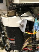
1990 Dual Force 120s one side showing 16.7v at speed with dual batteries

dingbat

Supreme Mariner
Joined
Nov 20, 2001
Messages
16,147
On your Force outboard?
Voltage regulators are simple generic circuits. Schematic is studied in electronics 101

VR dissipate excess voltage as heat. The issue is getting a unit large enough to dissipate the output as “heat” w/o melting. The 35 amp charging system on my 200 hp uses a water cooled regulator.

You could install the VR from a Ford pickup that would work on your Force Outboard
 

gica

Chief Petty Officer
Joined
Feb 24, 2016
Messages
496
Voltage regulators are simple generic circuits. Schematic is studied in electronics 101

VR dissipate excess voltage as heat. The issue is getting a unit large enough to dissipate the output as “heat” w/o melting. The 35 amp charging system on my 200 hp uses a water cooled regulator.

You could install the VR from a Ford pickup that would work on your Force Outboard
Can you give me a part number for reference and is it the 4 or 5 connectors? Also I assume that this won't handle the deep cycle batyeries either. The ones I looked at on eBay have one positive conector and one stator plus ground and ignition.
How do you connect the 2 stator and tach. Tach can actually go on the stator wire right?
YesterdayI bought a Mercury MERCURY MARINER OUTBOARD VOLTAGE REGULATOR 815279-4 (Q66) 20amp. It's a 4 wire.
Let me know on the Ford please. Thanks
 
Last edited:

Jiggz

Captain
Joined
Oct 23, 2009
Messages
3,909
Can you give me a part number for reference and is it the 4 or 5 connectors? Also I assume that this won't handle the deep cycle batyeries either. The ones I looked at on eBay have one positive conector and one stator plus ground and ignition.
How do you connect the 2 stator and tach. Tach can actually go on the stator wire right?
YesterdayI bought a Mercury MERCURY MARINER OUTBOARD VOLTAGE REGULATOR 815279-4 (Q66) 20amp. It's a 4 wire.
Let me know on the Ford please. Thanks
This should work for you. Note the gray wire is not a negative wire but most likely for tach connections. The body is the negative connection, meaning it should be grounded properly. Note some people mounts this with the epoxy side against the engine block while others put the aluminum side against the block. The aluminum side is also a heat sink for the unit. Putting it against the block makes sense except that when the engine is running, the engine block also gets hot mitigating heat dissipation. So putting the epoxy side against the block makes more sense except now heat dissipation is only thru air instead of metal to metal. Using heat sink fins will improve heat dissipation.
 

gica

Chief Petty Officer
Joined
Feb 24, 2016
Messages
496
This should work for you. Note the gray wire is not a negative wire but most likely for tach connections. The body is the negative connection, meaning it should be grounded properly. Note some people mounts this with the epoxy side against the engine block while others put the aluminum side against the block. The aluminum side is also a heat sink for the unit. Putting it against the block makes sense except that when the engine is running, the engine block also gets hot mitigating heat dissipation. So putting the epoxy side against the block makes more sense except now heat dissipation is only thru air instead of metal to metal. Using heat sink fins will improve heat dissipation.
I got to look for some pc procesor fan heat sink maybe with the fan attached to cool it. Imagine? I think it needs 5v not 12 could be wrong
 

topgun3690

Lieutenant Junior Grade
Joined
May 7, 2019
Messages
1,053
I mounted the new VR in the same spot as the original rectifier.....which is on the starter bracket which is out away from the engine block, so not directly in contact with the block heat.....which really doesn't get that hot anyway. Not sure how the rectifier on your Force 120 is mounted but it may be mounted the same? I put some heat transfer paste on the back of the VR before mounting it. Been on there several years with no issues......FYI
 

Attachments

  • IMG_1074 (2).jpg
    IMG_1074 (2).jpg
    934 KB · Views: 7

gica

Chief Petty Officer
Joined
Feb 24, 2016
Messages
496
I mounted the new VR in the same spot as the original rectifier.....which is on the starter bracket which is out away from the engine block, so not directly in contact with the block heat.....which really doesn't get that hot anyway. Not sure how the rectifier on your Force 120 is mounted but it may be mounted the same? I put some heat transfer paste on the back of the VR before mounting it. Been on there several years with no issues......FYI
I included some pictures on the previous page but it is mounted the same way as yours. Except it is with the epoxy towards the motor. The heat paste is a good idea I thought of that aswell.
I am sure my main problem was with the batteries even though only starboard motor showed overcharging.
 

Jiggz

Captain
Joined
Oct 23, 2009
Messages
3,909
I got to look for some pc procesor fan heat sink maybe with the fan attached to cool it. Imagine? I think it needs 5v not 12 could be wrong
No need for a fan. In fact, not even with heat sink, although that'll be nice. Try mounting it first like the Port side and then test. During test run, after about 5 minutes of WOT and charging accordingly, turn off motor, remove cowling and feel (aluminum backing) if the VR is getting hot. Hot means you cannot put your bare hand on it for more than 5 seconds. Very hot is like 3 seconds.
 

gica

Chief Petty Officer
Joined
Feb 24, 2016
Messages
496
No need for a fan. In fact, not even with heat sink, although that'll be nice. Try mounting it first like the Port side and then test. During test run, after about 5 minutes of WOT and charging accordingly, turn off motor, remove cowling and feel (aluminum backing) if the VR is getting hot. Hot means you cannot put your bare hand on it for more than 5 seconds. Very hot is like 3 seconds.
The spot it goes on is right by the starter on the port side. I will test the temp with a laser tester when I take it on water again hopefully this weekend.
 

gica

Chief Petty Officer
Joined
Feb 24, 2016
Messages
496
Hey guys sorry for being MIA on this. So today I went ahead and changed the switches on both sides. I now have the BlueSea 7650 on/off with ACR. I pretty much rewired the area. I will show pics. I briefly started the motors afterwards and one shows 13.5 or 14 at idle that's the starboard
while the port shows a bit above 12v. It was a quick though. I have not rested power at the gauge or ignition. Sometime this week I want to take the boat out. I don't know if you guys are familiar with the 7650 but it has seperate sides for house and start with an ACR. I haven't grasped the full explanation on the functionality yet.
 

Attachments

  • IMG_2044.jpeg
    5 MB · Views: 5
  • IMG_2043.jpeg
    4.4 MB · Views: 6

dingbat

Supreme Mariner
Joined
Nov 20, 2001
Messages
16,147
I don't know if you guys are familiar with the 7650 but it has seperate sides for house and start with an ACR. I haven't grasped the full explanation on the functionality yet.
It wired correctly, it allows you to “Combine”
the two batteries to start the motor
 
Last edited:
Top